Arrangement and method of imaging one-dimensional and two-dimensional optical codes at a plurality of focal planes

a technology of optical codes and focal planes, applied in the field of imaging, can solve the problems of high cost, high cost, and inability to meet the needs of imaging arrangements, and achieve the effect of avoiding the need for constant maintenan

Active Publication Date: 2007-05-29
SYMBOL TECH LLC
View PDF11 Cites 110 Cited by
  • Summary
  • Abstract
  • Description
  • Claims
  • Application Information

AI Technical Summary

Benefits of technology

[0011]Yet another aspect of the present invention is to provide an inexpensive image-based barcode reader for reading one-dimensional and two-dimensional symbols, labels, markings, pictures, etc. and performance levels which are equivalent to or exceed the performance levels associated with conventional laser-based optical code scanners designed for imaging and decoding similar symbols.
[0012]The imaging arrangement and barcode imager of the present invention achieve these and other aspects by providing an extended working range (i.e., greater than 61 cm or 24 inches) of approximately 5–102 cm (˜2–40 inches) compared to a typical working range of approximately 5–61 cm (˜2–24 inches) for conventional barcode imagers. The imaging arrangement and image-based barcode imager of the present invention do not require complex automatic-focusing systems. As such, the performance of the image-based barcode imager of the present invention in imaging and decoding one-dimensional and two-dimensional barcode symbols (and in imaging and processing labels, markings, pictures, etc.) is comparable to or even greater than conventional laser-based barcode readers and image-based barcode imagers.

Problems solved by technology

Furthermore, the aiming axis is often misaligned with the imaging axis of the imaging device.
However, the operator is still required to position the imaging device within the proper range and angle to produce an adequately sharp, i.e., substantially focused image.
In many applications where an increased working range is necessary, expensive and complex imaging arrangements having state-of-the-art automatic focus systems, such as zoom capabilities, are generally incorporated within or used in conjunction with barcode imagers to increase their working range.
However, such imaging arrangements, besides being expensive, generally require constant maintenance.
Therefore, when an application calls for imaging and decoding one-dimensional and two-dimensional barcode symbols, these imaging arrangements do not compete well in the marketplace against laser-based barcode readers which have comparable or even greater working ranges, and generally are less expensive.

Method used


Image

  • Arrangement and method of imaging one-dimensional and two-dimensional optical codes at a plurality of focal planes
  • Arrangement and method of imaging one-dimensional and two-dimensional optical codes at a plurality of focal planes
  • Arrangement and method of imaging one-dimensional and two-dimensional optical codes at a plurality of focal planes

Examples


Embodiment Construction

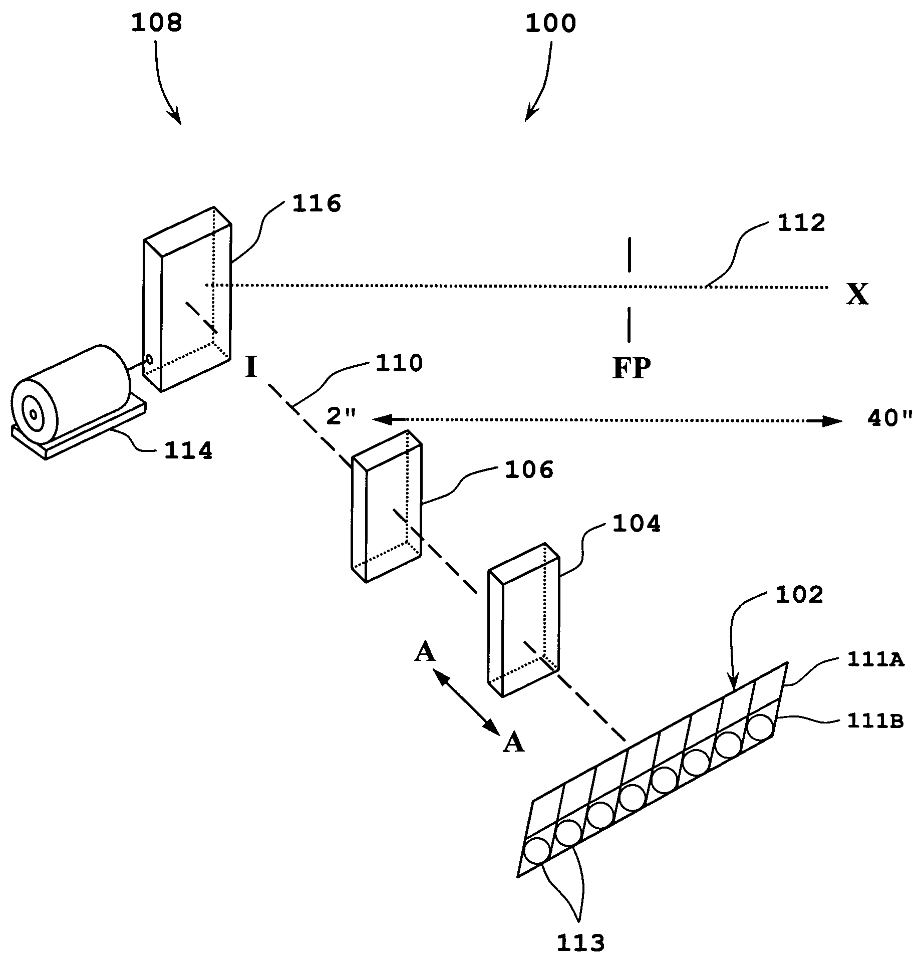
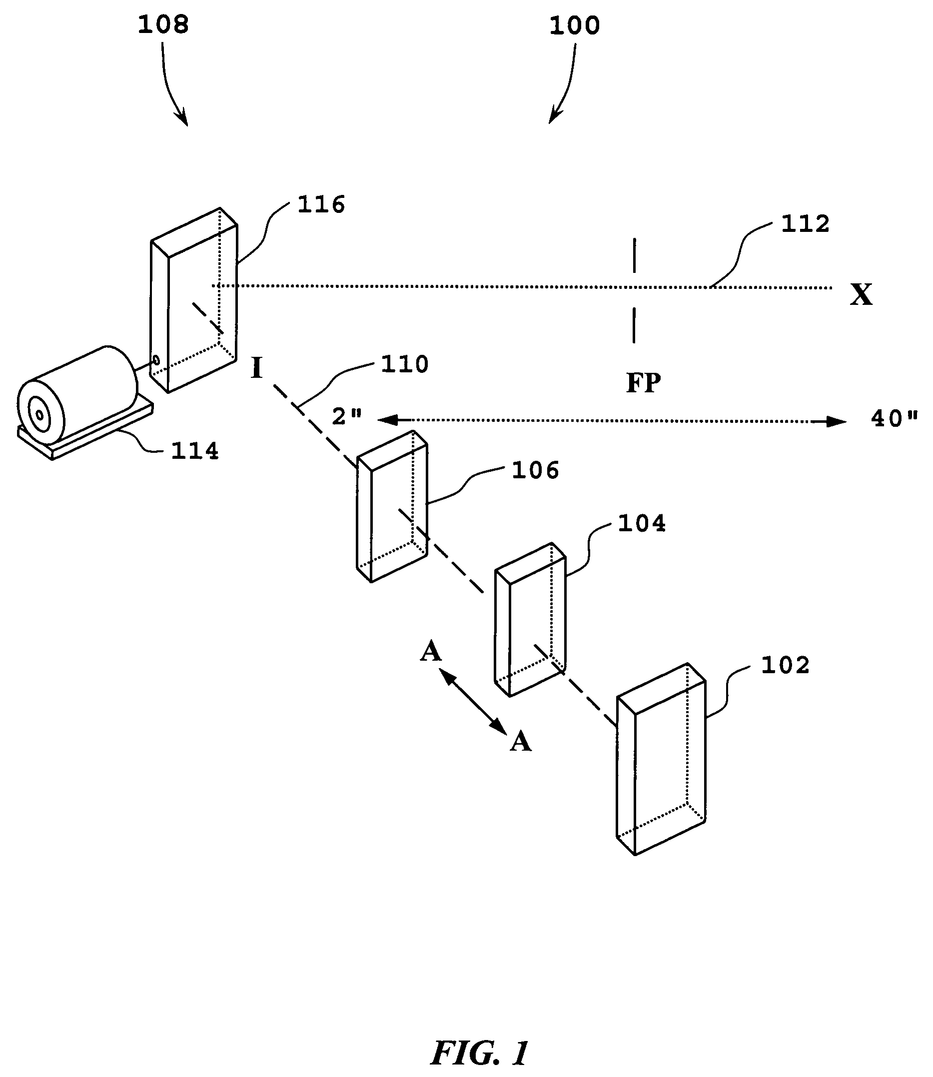
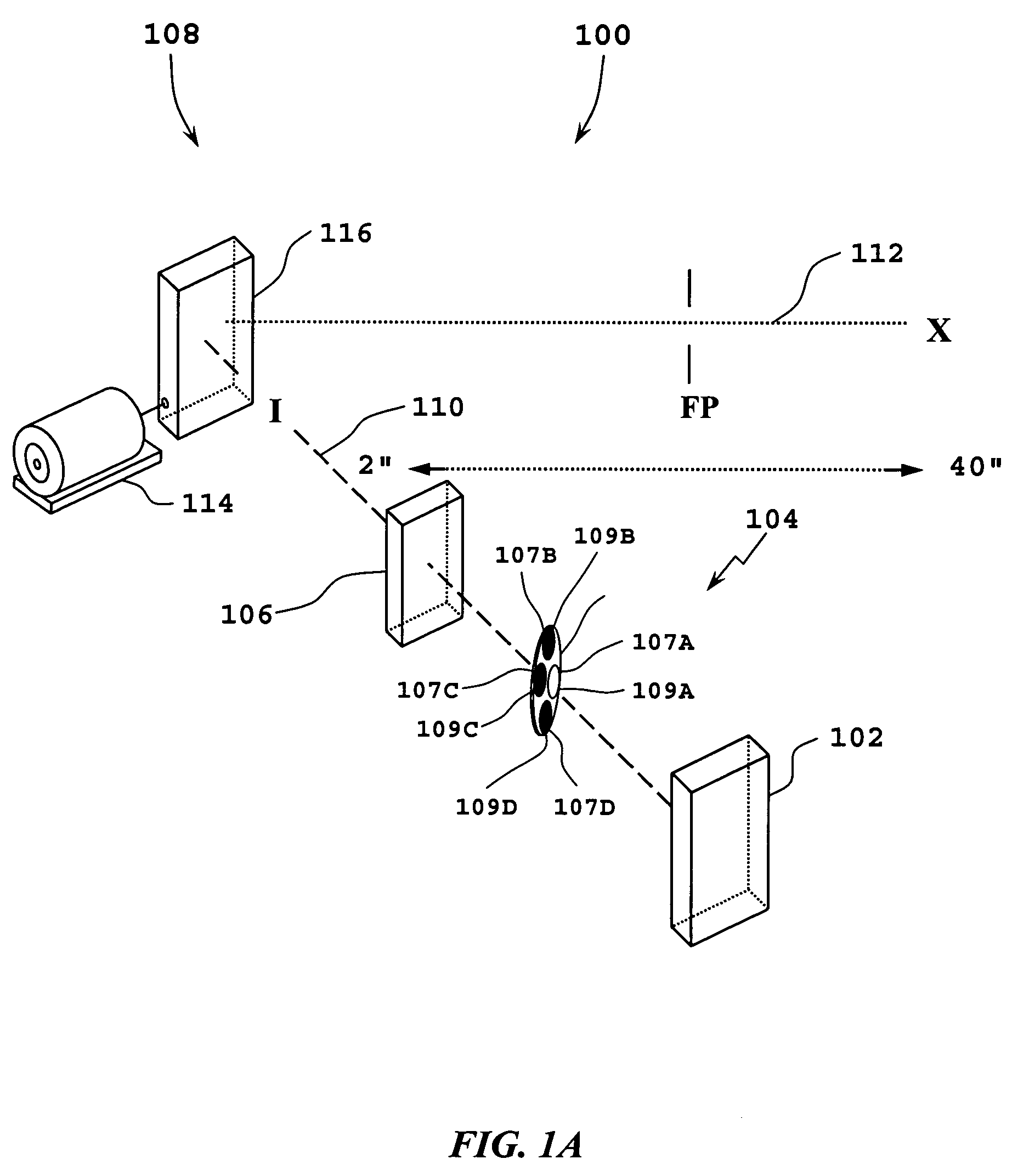
[0020]The imaging arrangements shown by the figures and described herein are suitable for imaging various optical codes or targets, such as labels, markings, pictures, etc., and especially suitable for imaging one-dimensional and two-dimensional barcode symbols, such as a Universal Product Code (UPC) barcode, and have an extended working range (i.e., greater than 61 cm or 24 inches) of approximately 5 cm (˜2 inches) to 102 cm (˜40 inches).

[0021]Referring initially to FIG. 1, an imaging arrangement in accordance with the present invention is illustrated. Imaging arrangement 100 includes an image sensor 102, an optical element 104, an optics assembly 106 and a mirror assembly 108. Each of the components of the imaging arrangement 100 is aligned along an imaging axis I, which is also identified by reference numeral 110. Imaging axis 110 is parallel to arrow A—A. The imaging axis 110 intersects an optical axis X, which is also identified by reference numeral 112.

[0022]Image sensor 102 i...


PUM


Abstract

A non-complex imaging arrangement is aligned along an imaging axis. A mirror assembly is configured to reflect an image from an optical axis, which intersects the imaging axis, toward the optics assembly. The imaging arrangement includes at least one fixed image sensor for imaging thereon an optical code or target, such as a one-dimensional or two-dimensional barcode symbol, or label, signature, marking, picture, etc. The imaging arrangement provides an extended working range of approximately 5–102 cm. The imaging arrangement is capable of being incorporated within a barcode imager to provide a non-complex barcode imager having an extended working range which is comparable to or greater than the working ranges of conventional image-based barcode imagers.

Description

PRIORITY[0001]The present application claims priority to a U.S. Provisional Application filed on Jul. 9, 2003 and assigned U.S. patent application Ser. No. 60 / 485,685, incorporated herein in its entirety.BACKGROUND OF THE INVENTION[0002]1. Field of the Invention[0003]The present invention relates to the field of imaging, and specifically to an imaging arrangement and barcode imager for imaging an optical code or target at a plurality of focal planes.[0004]2. Description of the Related Art[0005]CCD or CMOS-based imaging devices, such as conventional barcode imagers, generally have limited working ranges on the order of 5–61 cm (˜2–24 inches). Furthermore, the aiming axis is often misaligned with the imaging axis of the imaging device. In many cases, the imaging device is designed to be handheld or at least moveable within a given area, thus compensating, somewhat, for the limited working range and skewed axis. However, the operator is still required to position the imaging device wit...

Claims


Application Information

Patent Timeline
Patent Type & Authority Patents(United States)
IPC IPC(8): G02B26/08G06K7/10
CPCG06K7/10722G06K7/10801
Inventor PATEL, MEHUL
Owner SYMBOL TECH LLC
Why Eureka
Try Eureka