Dustproof receptacle connector

a technology for receptacle connectors and dust-proof receptacles, which is applied in the direction of coupling bases/cases, coupling device connections, electrical devices, etc., can solve the problem that prior dust-proof receptacle connectors cannot provide a reliable dust-proof function, and achieve the effect of avoiding lateral spring deformation

Inactive Publication Date: 2007-05-29
CHENG UEI PRECISION IND CO LTD
View PDF5 Cites 19 Cited by
  • Summary
  • Abstract
  • Description
  • Claims
  • Application Information

AI Technical Summary

Benefits of technology

[0008]In the dustproof receptacle connector of the present invention, with the design of the longitudinal pillar extending into the corresponding mounting hole and the spring retained entirely on the pillar, the lateral deformation of the spring can be avoided. In addition, the mounting hole ensures that the longitudinal pillar only slide in the longitudinal direction, thereby the dustproof cover can steadily and appropriately slide in the receiving cavity. Consequently, the dustproof receptacle connector of the present invention is qualified to keep from the contamination.

Problems solved by technology

However, in these prior connectors, each spring is positioned between the projecting pillar of the dustproof cover and the mounting hole of the housing only by two ends of the spring, so the main body of the spring easily oscillates laterally and cause the unsteady sliding of the dustproof cover as the mating plug connector being inserted into the receptacle connector, and furthermore the unsteady sliding of the dustproof cover results in bad dustproof function during the dustproof cover sliding back by the resilience of the springs to seal the front opening of the receptacle connector again.
Therefore, the prior dustproof receptacle connector cannot provide a reliable dustproof function.

Method used


Image

  • Dustproof receptacle connector
  • Dustproof receptacle connector
  • Dustproof receptacle connector

Examples


Embodiment Construction

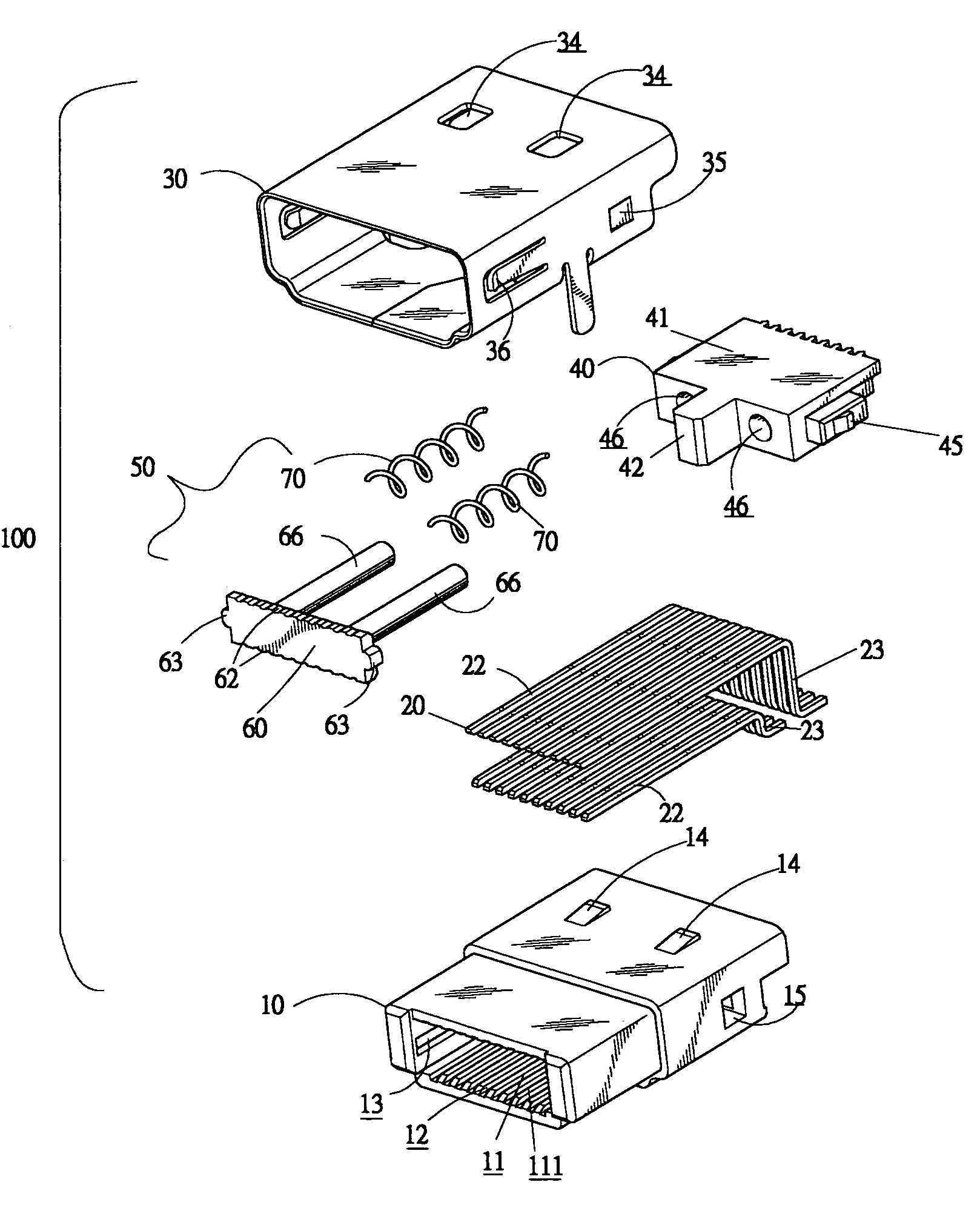
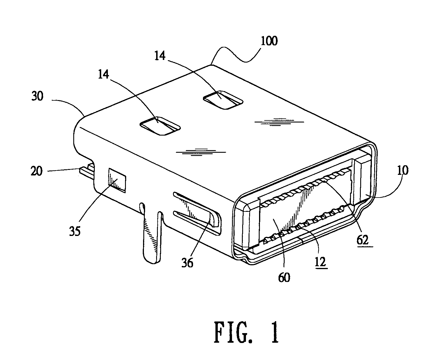
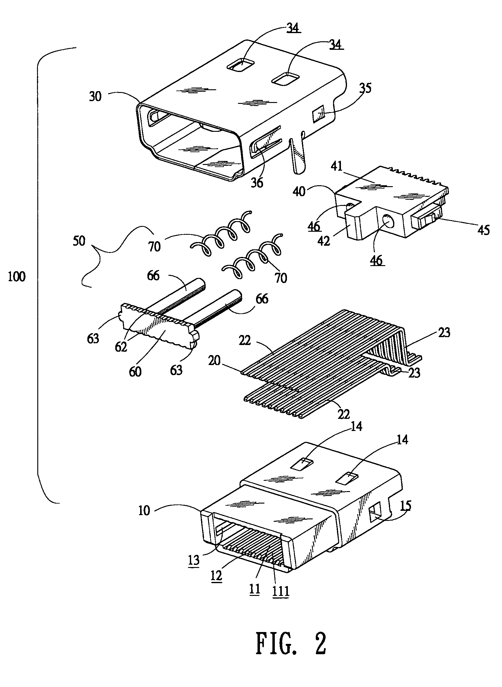
[0017]With reference to FIGS. 1 and 2, a dustproof receptacle connector 100 in accordance with the present invention comprises a dielectric housing 10, a female shield 30 encircling the housing 10, a plurality of female contacts 20 and a slider unit 50 which are both disposed in the housing 10.

[0018]As shown in FIG. 2, the housing 10 has a top wall, a bottom wall opposite the top wall, two opposite side walls disposed between the top and bottom walls, and a rear wall disposed at the rear end of the prior four walls, together with a receiving cavity 11 defined therebetween. The receiving cavity 11 further has a front opening 111 defined in the front surface of the housing 10. A plurality of contact grooves 12 is respectively defined in inner surface of the top and bottom walls of the housing 10 in juxtaposed relation for holding the corresponding female contacts 20 and communicates with the receiving cavity 11. Two elongated guiding slots 13 with each having a closed front end are re...


PUM


Abstract

A dustproof receptacle connector includes a dielectric housing, a plurality of female contacts disposed in the housing, and a slider unit installed in the housing. The housing has a receiving cavity with a front opening defined in a front surface thereof, and a pair of mounting holes defined in a rear wall of the housing communicating with the receiving cavity. The slider unit includes a dustproof cover slidably received in the receiving cavity for sealing the front opening and a pair of springs disposed on the dustproof cover. A pair of longitudinal pillars extending backwards from the dustproof cover, with the free end of each pillar slidably disposed in the corresponding mounting hole of the housing. Each spring is retained on the corresponding longitudinal pillar, with one end thereof abutting against the dustproof cover and the other end thereof abutting against the rear wall of the housing.

Description

BACKGROUND OF THE INVENTION[0001]1. Field of the Invention[0002]This invention generally relates to a receptacle connector and, particularly, to a dustproof receptacle connector.[0003]2. The Related Art[0004]In the field of electronic connectors, a type of connector is designed with dustproof function in order to avoid the deterioration of electrical connection even short circuit, which are caused by contamination.[0005]Japan patent NO. 2004-31186 issued on Jan. 29, 2004, disclosed a dustproof receptacle connector, which includes a female shield, a housing enclosed by the female shield, and a plurality of female contacts disposed in the housing. The housing has a receiving cavity with a front opening defined in a front surface thereof. A dustproof cover is slidably received in the receiving cavity for sealing the front opening, with two projecting pillars extending rearwards from the rear surface thereof. Correspondingly, two mounting holes are defined in a rear wall of the housing,...

Claims


Application Information

Patent Timeline
Patent Type & Authority Patents(United States)
IPC IPC(8): H01R13/44H01R13/453H01R13/52H01R13/658
CPCH01R13/4538H01R13/5213H01R13/6582
Inventor CHIANG, SHU MANHUANG, CHUNG HSINKAO, YI CHIUSU, YU-HUNG
Owner CHENG UEI PRECISION IND CO LTD
Why Eureka
Try Eureka