Anti-twist casing for endoscopic manipulating head assembly

a technology of manipulating head and endoscope, which is applied in the field of endoscopes, can solve the problems of inevitably increasing the weight of the manipulating head assembly, the inability to directly connect the reinforcing member, and the inability to resist the twisting mechanism of the grip cover by the above-mentioned prior ar

Inactive Publication Date: 2007-05-29
FUJI PHOTO OPTICAL CO LTD
View PDF3 Cites 70 Cited by
  • Summary
  • Abstract
  • Description
  • Claims
  • Application Information

AI Technical Summary

Benefits of technology

[0009]In view of the foregoing situations, it is an object of the present invention to provide a casing for an endoscopic manipulating head assembly, which is provided with anti-twist lock portions to prevent twisting or rotational movements of a grip cover section of the casing.
[0010]It is another object of the present invention to provide a casing of the sort mentioned above, which is largely constituted by a main cover section and a grip cover section both formed of a synthetic resin material to provide a lightweight casing and which is arranged to enhance the strength of the grip cover section despite a reduction in wall thickness.

Problems solved by technology

The grip cover anti-twist mechanism by the above-mentioned prior art however still has a number of problems.
Particularly in a case where the grip section of the casing is formed approximately in a circular shape in section, a difficult machining operation is required to provide a flat surface on the inner side of the grip cover section, and the weight of the manipulating head assembly is inevitably increased for this reason.
Besides, difficulties are encountered in directly connecting the reinforcing member, which is provided across the main cover section and the grip cover section of the casing, to the reinforcing tube which is provided internally of the divisional cover section.
In addition to an increased number of parts, the use of the link member results in a restriction on the available internal space of the manipulating head assembly.

Method used


Image

  • Anti-twist casing for endoscopic manipulating head assembly
  • Anti-twist casing for endoscopic manipulating head assembly
  • Anti-twist casing for endoscopic manipulating head assembly

Examples


Embodiment Construction

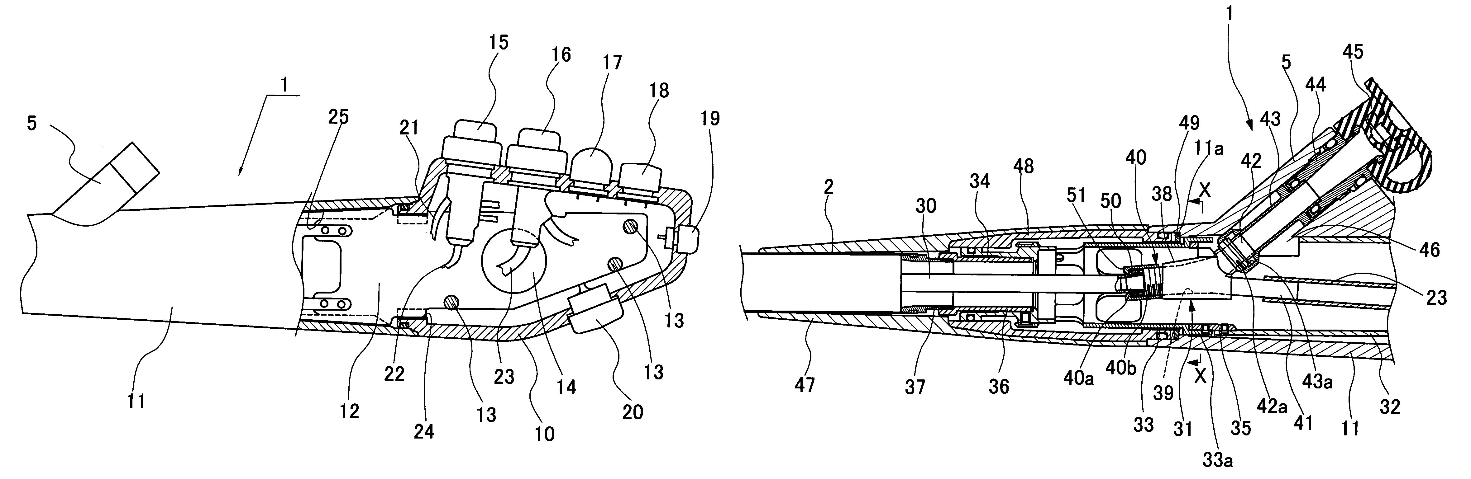
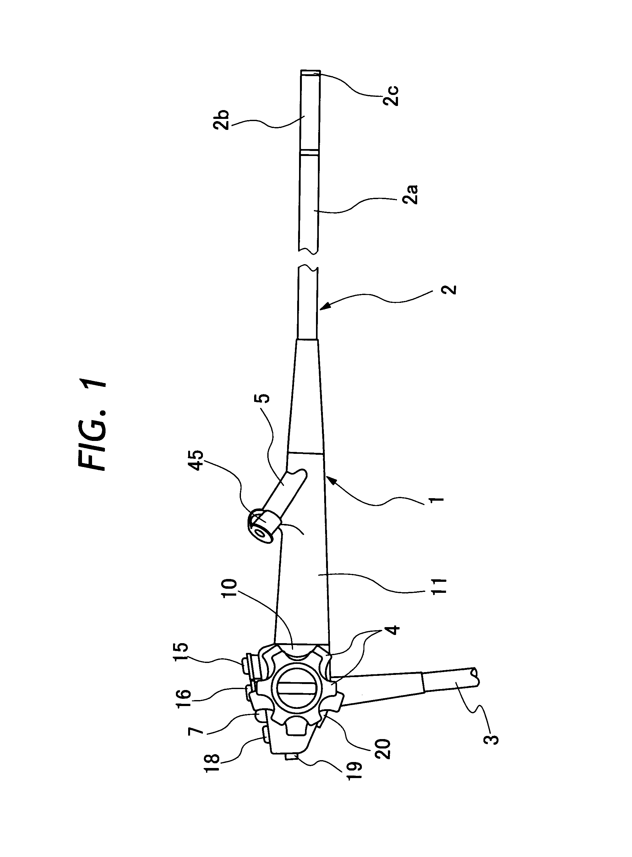
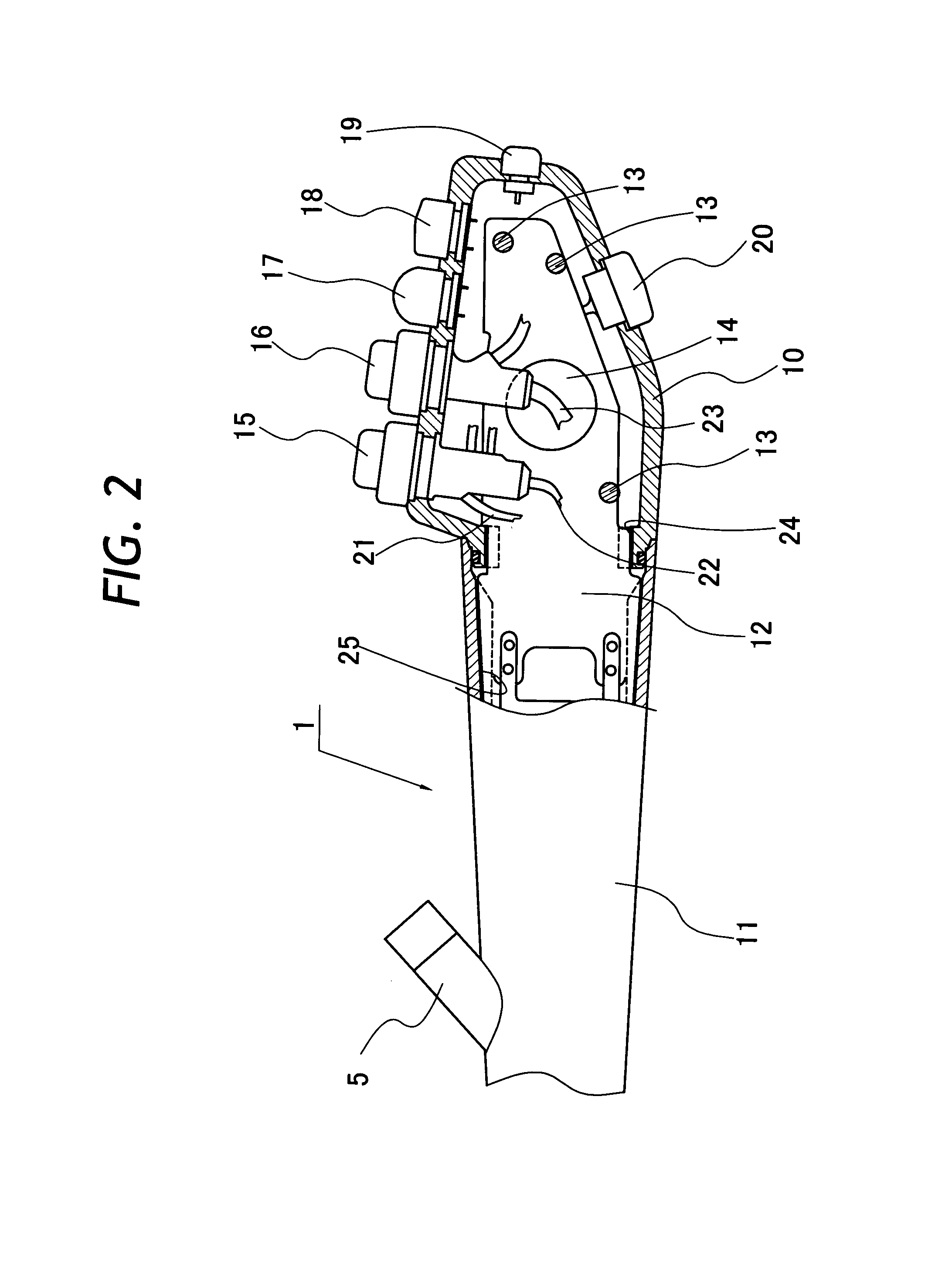
[0020]Hereafter, the present invention is described more particularly by way of its preferred embodiments. Referring first to FIG. 1, there is schematically shown the general layout of an endoscope. In that figure, indicated at 1 is a manipulating head assembly of the endoscope, at 2 an insertion tube, and at 3 a flexible light guide cable. From a proximal end which is connected to the manipulating head assembly 1, a major part of the insertion tube 2 consists of an elongated flexible body portion 2a which can be bent in arbitrary directions at the time of insertion into a body cavity. Successively connected to the fore end of the flexible body portion 2a are an angle section 2b and a rigid tip end section 2c. As well known in the art, illumination and observation windows are provided on the rigid tip end section 2c which can be turned into an arbitrary direction by angulation of the angle section 2c.

[0021]The angulation of the angle section 2b is controlled from the side of the ma...


PUM


Abstract

A casing of an endoscopic manipulating head assembly is largely constituted by and dividable into a main cover section adapted to support an operating means of an angulation control mechanism and a grip cover section provided between the main cover section and an insertion tube of the endoscope. Both of the main cover section and the grip cover section are formed of a synthetic resin material. A support plate of a rigid metal is provided internally of the manipulating head assembly to support the angulation control mechanism. A plural number of passage-forming tubular structural members are successively connected within the grip cover section for passing internal components to and from the insertion tube of the endoscope. The support plate is connected to one of the tubular structural members which is located at the proximal end of the grip cover section. A first anti-twist lock portion is formed between the support plate and joined end portions of the main and grip cover sections, while a second anti-twist lock portion is formed between the grip cover section and joined end portions of the tubular structural members.

Description

BACKGROUND OF THE INVENTION[0001]1. Field of the Art[0002]This invention relates generally to endoscopes for use in medical fields, and more particularly to a synthetic resin casing of a manipulating head assembly of an endoscope, which is so arranged as to prevent twisting or rotational movements of a grip cover section of the casing.[0003]2. Prior Art[0004]Generally, medical endoscopes are largely constituted by a manipulating head assembly to be gripped by an operator for manipulation of various operation control means, an elongated insertion tube connected to and extended out on the front side of the manipulating head assembly, and a universal cable led out from a rear side of the manipulating head assembly to connect a light guide in the universal cable to a light source. At least an illumination window and an observation window are provided on a rigid tip end section at the fore distal end of the insertion tube. Illumination light is projected forward through the illumination ...

Claims


Application Information

Patent Timeline
Patent Type & Authority Patents(United States)
IPC IPC(8): A61B1/00A61B1/005
CPCA61B1/0011A61B1/0052
Inventor AKIBA, HARUO
Owner FUJI PHOTO OPTICAL CO LTD
Why Eureka
Try Eureka