Accommodative intraocular lens

Active Publication Date: 2007-05-29
ALCON INC
View PDF20 Cites 130 Cited by
  • Summary
  • Abstract
  • Description
  • Claims
  • Application Information

AI Technical Summary

Benefits of technology

[0012]The present invention improves upon the prior art by providing a two-optic accommodative lens system. The first lens has a negative power and is located posteriorly within the capsular bag and laying against the posterior capsule. The periphery of the first lens contains a pair of generally T-shaped haptics oriented along a vertical meridian of the capsular bag and having a generally rectangular slot within the top portion of the “T”. The first lens further has a plurality of elongated haptics oriented along a horizontal meridia

Problems solved by technology

When age or disease causes the lens to become less transparent, vision deteriorates because of the diminished light which can be transmitted to the retina.
As a result, the natural lens tends to flatten.
As the lens ages, it becomes harder and is less able to change shape in reaction to the tightening of the ciliary muscle.
This makes it harder for the lens to focus on near objects, a medical condition known as presbyopia.
Advanced Medical Optics has bee

Method used


Image

  • Accommodative intraocular lens
  • Accommodative intraocular lens
  • Accommodative intraocular lens

Examples


second embodiment

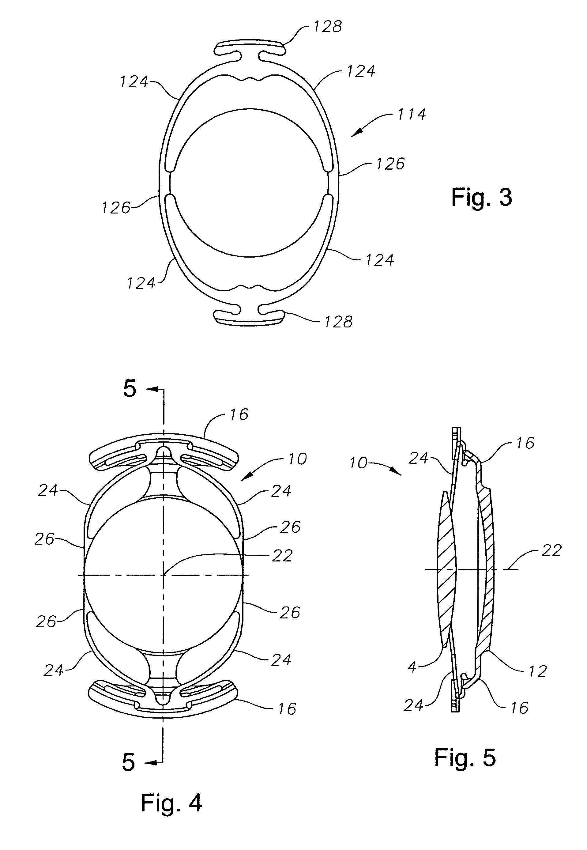
[0039]As best seen in FIG. 3, in a second embodiment, anterior optic 114 is of similar construction as optic 14, having haptics 124 that are connected to optic 114 by hinge regions 126 and containing notched tabs 128 carried at the distal ends of haptics 124. Tabs 128 are sized and shaped to fit within slots 18 on optic 12, thereby holding optic 114 firmly within optic 12 while still permitting rotation of locking tabs 128 within slots 18.

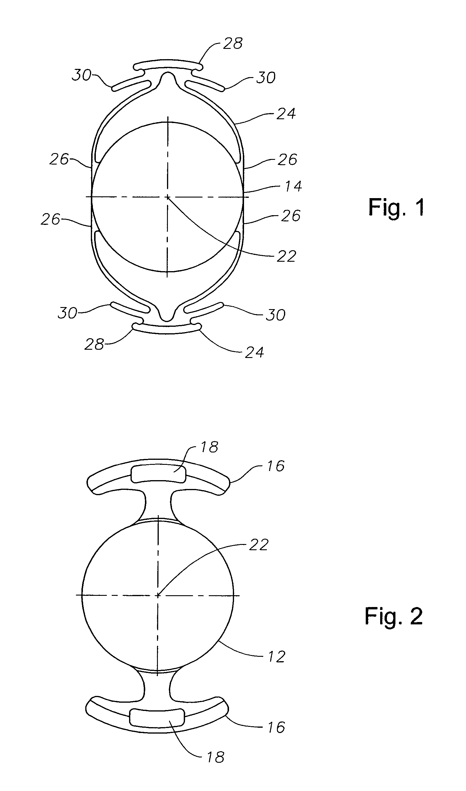
[0040]As best seen in FIG. 6, in a second embodiment, posterior optic 112 is of similar construction as optic 12, being generally symmetrical about optical axis 22 and containing opposing, generally T-shaped haptics 116 that are shaped to stretch and fill the equatorial region of the capsular bag. Hap tics 116 contain slots 118.

third embodiment

[0041]As best seen in FIG. 8, in the present invention, optic 212 is generally symmetrical about optical axis 22 and contains opposing, generally T-shaped haptics 216 that are shaped to stretch and fill the equatorial region of the capsular bag. Haptics 216 contain slots 218 that penetrate all the way through haptics 216. As best seen in FIG. 7, optic 214 contains a plurality of haptics 224 that are connected to optic 214 by hinge regions 226 and contain notched tabs 228 carried at the distal ends of haptics 224. Tabs 228 are sized and shaped to fit within slots 218 on optic 212, thereby holding optic 214 firmly within optic 212 while still permitting rotation of locking tabs 228 within slots 218. One skilled in the art will recognize that slots 218 may be located on haptics 224 and that tabs 228 may be located on optic 212.

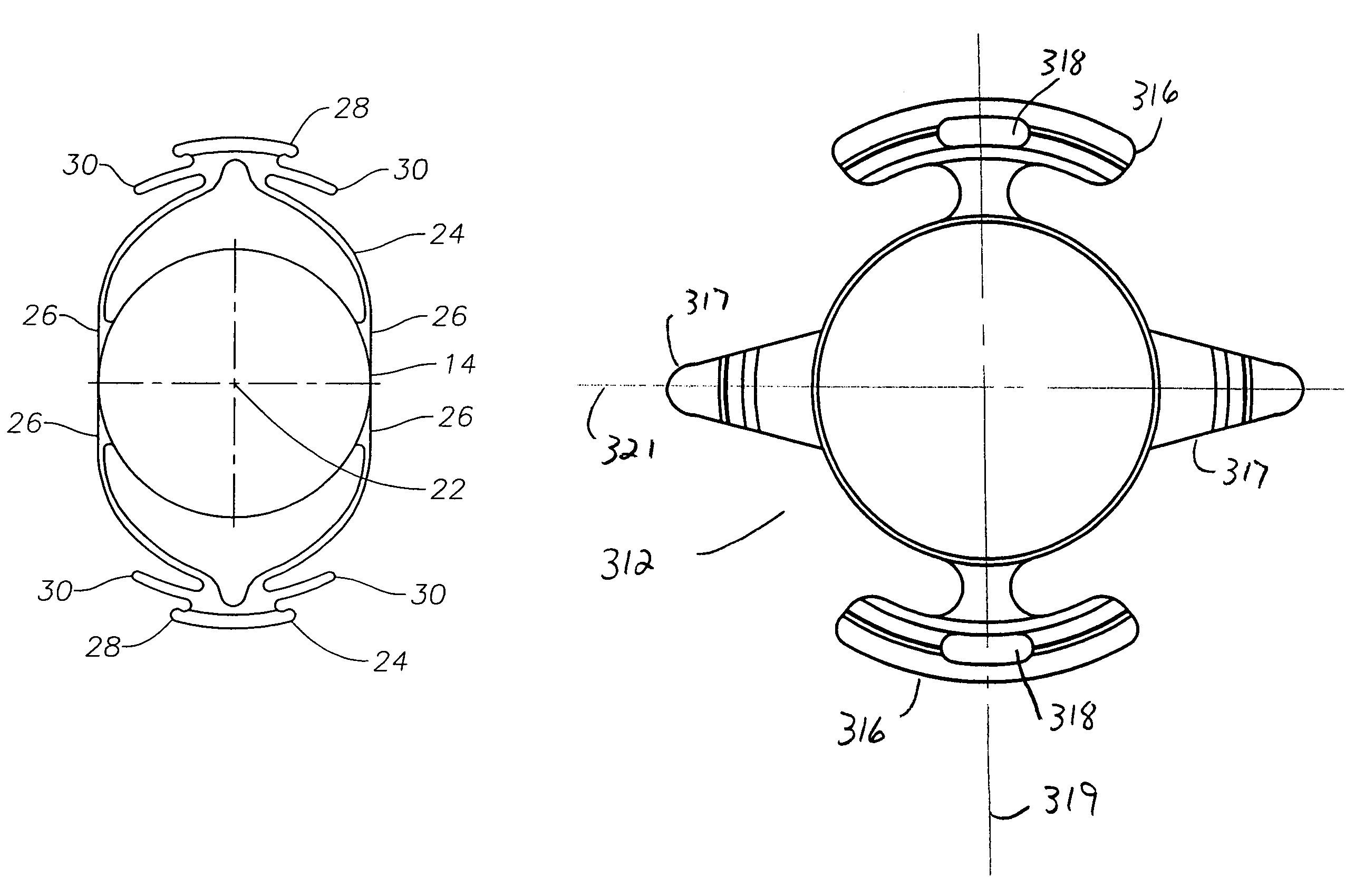
[0042]As best seen in FIGS. 9, 10 and 11, optic 312 is generally symmetrical about optical axis 22 and contains opposing, generally T-shaped haptics 316 that are...


PUM


Abstract

A two-optic accommodative lens system. The first lens has a negative power and is located posteriorly within the capsular bag and laying against the posterior capsule. The periphery of the first lens contains a pair of generally T-shaped haptics oriented along a vertical meridian of the capsular bag and having a generally rectangular slot within the top portion of the “T”. The first lens further having a plurality of elongated haptics oriented along a horizontal meridian of the capsular bag. The second lens is located anteriorly to the first lens outside of the capsular bag and is of a positive power. The peripheral edge of the second lens contains a pair of encircling haptics having a notched tab sized and shape to fit within the slots in the haptics on the first lens to lock the second lens onto the first lens. Hinge structures on the encircling haptics allow the second lens to move relative to the first lens along the optical axis of the lens system in reaction to movement of the ciliary muscle.

Description

[0001]This application is a continuation-in-part of U.S. patent application Ser. No. 10 / 442,771, filed May 21, 2003, now U.S. Pat. No. 7,029,497.BACKGROUND OF THE INVENTION[0002]This invention relates generally to the field of intraocular lenses (IOL) and, more particularly, to accommodative IOLs.[0003]The human eye in its simplest terms functions to provide vision by transmitting light through a clear outer portion called the cornea, and focusing the image by way of a crystalline lens onto a retina. The quality of the focused image depends on many factors including the size and shape of the eye, and the transparency of the cornea and the lens.[0004]When age or disease causes the lens to become less transparent, vision deteriorates because of the diminished light which can be transmitted to the retina. This deficiency in the lens of the eye is medically known as a cataract. An accepted treatment for this condition is surgical removal of the lens and replacement of the lens function ...

Claims


Application Information

Patent Timeline
IPC IPC(8): A61F2/16
CPCA61F2/1613A61F2/1629A61F2/1648A61F2002/1681
Inventor ZHANG, XIAOXIAOYANG, YIN
Owner ALCON INC
Why Eureka
Try Eureka