RF and pulse bias tee

a pulse bias tee and pulse bias technology, applied in the field of rf and, can solve the problems of measurement errors, calibration difficulties, measurement errors, etc., and the device may not be able to withstand continuous application of the dc and/or rf signals employed

Inactive Publication Date: 2007-05-29
KEITHLEY INSTRUMENTS INC
View PDF5 Cites 2 Cited by
  • Summary
  • Abstract
  • Description
  • Claims
  • Application Information

AI Technical Summary

Benefits of technology

[0005]A RF and pulse bias tee for use with a source measure unit (SMU) includes a SMU source terminal; a SMU measure terminal; an output terminal; a SMU measure terminal pulse/RF frequency block between the SMU measure terminal and the output terminal; a SMU source terminal high frequency bl

Problems solved by technology

In some necessary measurements, a device may not be able to withstand continuous application of the DC and/or RF signals employed.
In other cases, at minimum, the continuous application

Method used


Image

  • RF and pulse bias tee
  • RF and pulse bias tee
  • RF and pulse bias tee

Examples


Embodiment Construction

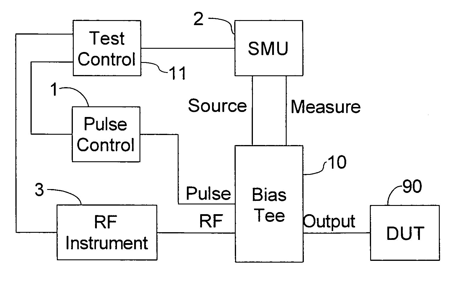
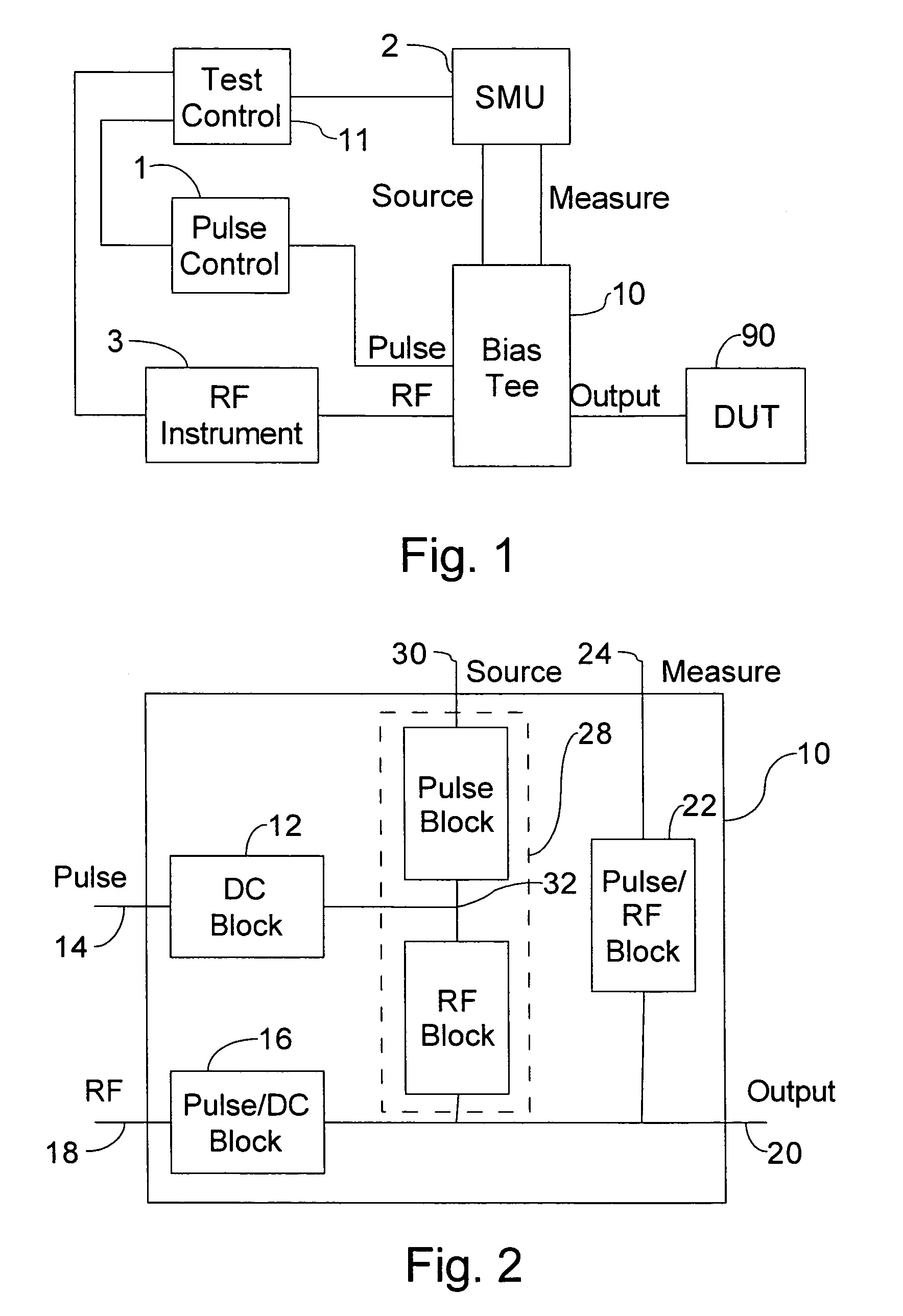
[0009]Referring to FIG. 1, a pulse control 1, a SMU 2 and a RF instrument 3 are provided for testing devices. The pulse control 1 provides pulses to a pulse input of a RF and pulse bias tee 10 according to a desired pulse repetition rate and other pulse characteristics. The SMU 2 has a source terminal and a measure terminal connected to respective source and measure terminals on the bias tee 10. The RF instrument 3 has a RF output connected to a RF input on the bias tee 10. The bias tee 10 has an output connected to a DUT 90.

[0010]The bias tee 10 keeps DC from the SMU 2 out of the RF instrument 3 and the pulse control 1. The bias tee 10 keeps RF from the RF instrument 3 out of the SMU 2 and the pulse control 1. The bias tee 10 also keeps the pulse train from the pulse control 1 out of the SMU 2 and the RF instrument 3. Meanwhile, the bias tee 10 allows any of the input signals to be applied to the DUT 90. The test controller 11 controls the operation of the pulse control 1, the SMU ...


PUM


Abstract

A RF and pulse bias tee for use with a source measure unit (SMU) includes a SMU source terminal; a SMU measure terminal; an output terminal; a SMU measure terminal pulse/RF block between the SMU measure terminal and the output terminal; a SMU source terminal high frequency block having two end nodes and an intermediate node, the end nodes being connected between the SMU source terminal and the output terminal; a RF input; a pulse/DC block between the RF input and the output terminal; a pulse input; and a DC block between the pulse input and the intermediate node.

Description

BACKGROUND OF THE INVENTION[0001]The present invention relates to the testing of electronic components and, in particular, to the testing of components in DC, RF and pulsed regimes.[0002]In some necessary measurements, a device may not be able to withstand continuous application of the DC and / or RF signals employed. In other cases, at minimum, the continuous application of the signals may produce heating of the device under test (DUT), resulting in measurement errors. To overcome this limitation, it is known to pulse the signals so that the average power applied is within tolerable limits.[0003]In the typical prior art approach to making RF and DC measurements on the same nodes of the DUT, switches are included in the test path to switch the RF and DC test instruments in and out of the circuit as appropriate. In high precision measurements, this results in errors and / or calibration difficulties. This is further compounded in the case of pulsed measurements.[0004]High precision DC te...

Claims


Application Information

Patent Timeline
IPC IPC(8): G01R31/28
CPCG01R31/2822G01R1/04
Inventor PRONIN, ALEXANDER N.
Owner KEITHLEY INSTRUMENTS INC
Why Eureka
Try Eureka