High-frequency magnetic spectrograph

A spectrometer and high-frequency technology, applied in the field of material surface magnetic measurement, can solve the problems of inability to obtain magnetization dynamic information, inability to obtain nanoscale magnetization dynamic characteristics, imaging effect is easily limited by optical components, etc., to achieve fast test speed and use The effect of long life and simple installation

Inactive Publication Date: 2018-07-27
JINHUA VOCATIONAL TECH COLLEGE
View PDF0 Cites 2 Cited by
  • Summary
  • Abstract
  • Description
  • Claims
  • Application Information

AI Technical Summary

Problems solved by technology

The magneto-optical Kerr effect measurement device mainly detects the magnetization observation of the sample surface by detecting the change of the polarization state of a beam of linearly polarized light after it is reflected on the surface of the material. Therefore, the imaging effect is easily limited by the optical elements. Technical defect 1: The spatial resolution of the traditional focusing Kerr microscope using microscope objective lens is determined by the optical diffraction limit, so it is impossible to obtain the dynamic characteristics of magnetization at the nanometer scale; the existing technical defect 2: it is impossible to obtain higher frequency magnetization in the sample. Magnetization dynamic information, the high-frequency magnetic spectrometer can solve the problem

Method used


Image

  • High-frequency magnetic spectrograph
  • High-frequency magnetic spectrograph

Examples


Embodiment Construction

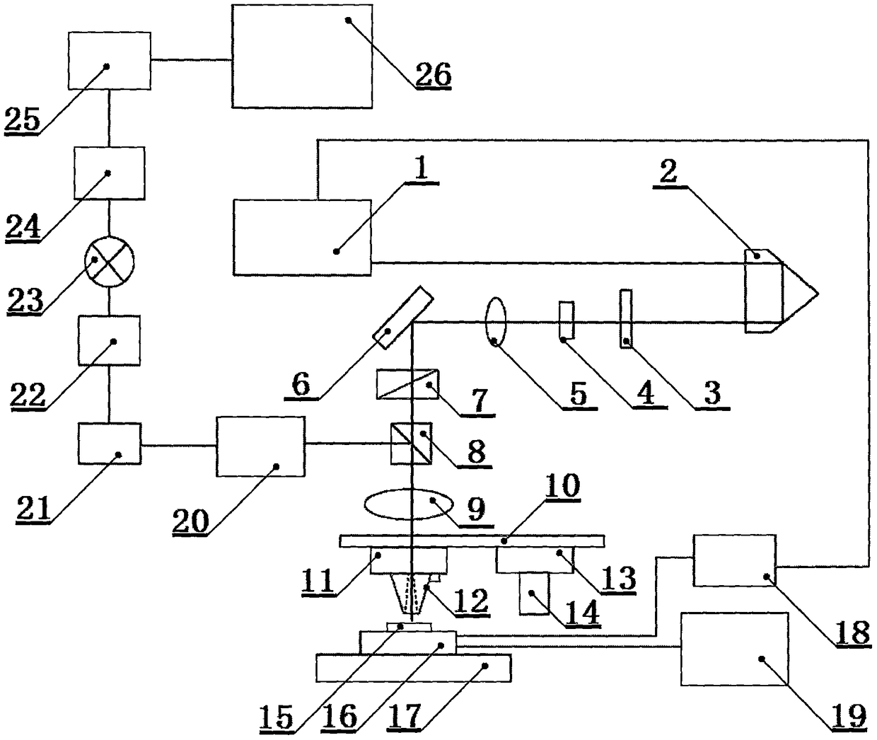
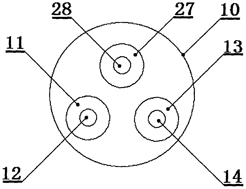
[0027] Such as figure 1 It is a schematic diagram of the present invention, the pulsed laser 1, the signal generator 18, the waveguide 16, and the oscilloscope 19 are connected by cables in turn, and the optical bridge detector 20, the bias tee 21, the amplifier I 22, the mixer 23, and the amplifier II 24, analog-to-digital converter 25, computer 26 cable connection successively, the laser beam that described pulse laser 1 emits successively through delayer 2, 1 / 4 wave plate 3, concave lens 4, convex lens 1 5, plane mirror 6, polarizer 7 , beam splitter 8, convex lens II 9, lens stand 10, atomic force microscope I11, probe I 12, thereby forming an incident light path, the reflected light generated by the laser beam irradiating on the surface of sample 15 passes through probe I 12, atomic force microscope in turn I 11, lens stand 10, convex lens II9, beam splitter 8, thereby forming a reflected light path, the reflected light is deflected to the optical bridge detector 20 by th...


PUM

PropertyMeasurementUnit
diameteraaaaaaaaaa
diameteraaaaaaaaaa
diameteraaaaaaaaaa

Abstract

The invention relates to the field of material surface magnetism measurement. A high-frequency magnetic spectrograph comprises a pulse laser, a time delayer, a 1 / 4 wave plate, a concave lens, a firstconvex lens, a plane mirror, a polaroid, a beam splitter, a second convex lens, a lens table, a first atomic force microscope, a first probe, a lens seat, an objective lens, a sample, a wave guide, asample table, a signal generator, an oscilloscope, a detector, a bias three-way valve, a first amplifier, a frequency mixer, a second amplifier, an analog-digital converter, a computer, a second atomic force microscope, a second probe and a phase sensitive detector. A single nanometer structure can be measured; the measurement on the magnetization dynamic state of the sample surface has the spaceresolution ratio of the submicron grade; the magnetization information on the nanometer scale sample surface is obtained by using a high-precision positioning device; two different atomic force microscope needle points are used for respectively performing contact mode atomic force microscope scanning and near field time resolution Magneto-Optical Kerr effect experiments; a frequency domain methodis used for detecting the GHz frequency band magnetization dynamic states on the surface of the sample.

Description

technical field [0001] The invention relates to the field of material surface magnetic measurement, in particular to a high-frequency magnetic spectrometer capable of measuring the high-frequency dynamic magnetization of a single nanostructure on the material surface. Background technique [0002] The magneto-optical Kerr effect measurement device is an important means in the study of material surface magnetism. Its working principle is based on the magneto-optic Kerr effect caused by the interaction between light and magnetized media. Magnetic detection, and non-contact measurement can be realized, and it has important applications in the research of magnetic order, magnetic anisotropy, interlayer coupling and phase transition behavior of magnetic ultrathin films. The magneto-optical Kerr effect measurement device mainly detects the magnetization observation of the sample surface by detecting the change of the polarization state of a beam of linearly polarized light after i...

Claims


Application Information

Patent Timeline
Patent Type & Authority Applications(China)
IPC IPC(8): G01N21/21G01N21/27
CPCG01N21/21G01N21/27G01N2021/218G01N2201/067
Inventor 张向平方晓华范晓雯
Owner JINHUA VOCATIONAL TECH COLLEGE
Why Eureka
Try Eureka