Experimental device and method based on pulsed Townsend method

An experimental device and pulse technology, applied in the direction of measuring devices, instruments, measuring electronics, etc., can solve the problems of the influence of experimental accuracy and low repeatability of electrode distance, and achieve the effect of fast analysis speed, high quantum efficiency and fast measurement

Pending Publication Date: 2020-12-15
XI AN JIAOTONG UNIV
View PDF4 Cites 1 Cited by
  • Summary
  • Abstract
  • Description
  • Claims
  • Application Information

AI Technical Summary

Problems solved by technology

[0009] The purpose of the present invention is to solve the problem that the traditional PT experimental device in the prior art often adopts a traditional mechanical structure in the control of the elec

Method used


Image

  • Experimental device and method based on pulsed Townsend method
  • Experimental device and method based on pulsed Townsend method
  • Experimental device and method based on pulsed Townsend method

Examples


Embodiment 1

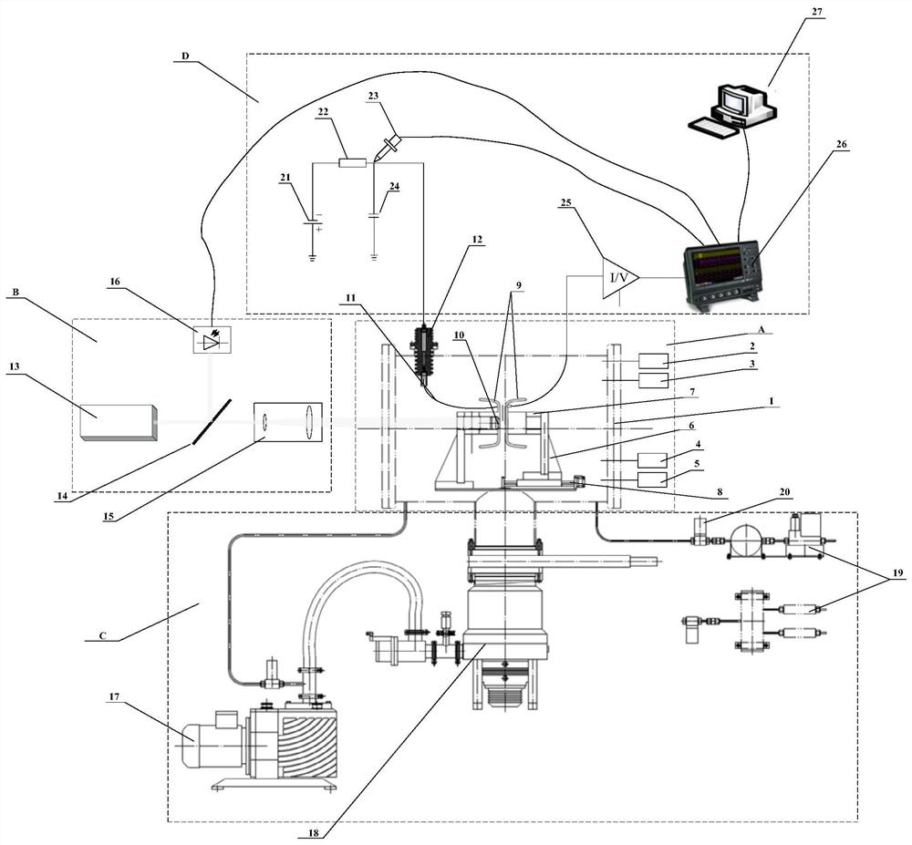
[0072] see figure 1 , the present invention is based on the pulse Thomson method experimental device, the device includes a vacuum chamber A, an optical system B, a vacuum system C and a measurement system D.

[0073] The vacuum cavity A is connected with the optical system B and the vacuum system C respectively. Optical system B is connected to measuring system D.

[0074] The vacuum chamber A includes a vacuum chamber 1, a first membrane gauge barometer 2, a second membrane gauge barometer 3, a micro-water content detector 4, a micro-oxygen content detector 5, an electrode support 6, an electrode insulating connector, Vacuum displacement stage 8 , Rogowski electrode 9 , photocathode coated glass 10 , high voltage cable 11 and insulating sleeve 12 .

[0075] The vacuum chamber 1 is a stainless steel chamber with a length and a diameter of 55 cm and a volume of about 130 liters.

[0076] One side of the vacuum chamber 1 is provided with a first thin-film gauge barometer 2 ,...

Embodiment 2

[0124] A kind of experimental data processing method based on pulse Thomson's method, concrete workflow of the present invention is as follows (taking the experiment to 10kPa pure carbon dioxide as example):

[0125] 1. Parameter setting.

[0126] Such as Figure 6 As shown in the work flow chart of the parameter setting link, first open the end cover of the cavity to replace the photocathode glass, then control the moving electrode to move to the static electrode until it is closed and tested for continuity by a multimeter, and then reset the distance to zero.

[0127] Next, after controlling the vacuum displacement table 8 to move the movable electrode to the desired set spacing position, the power supply of the vacuum displacement table 8 is cut off.

[0128] Turn on the mechanical pump 17 to evacuate the cavity below 8Pa, then turn on the molecular pump 18 and open the flapper valve to evacuate the vacuum chamber 1 to below 5×10⁻⁵.

[0129] Close the slide valve and the ...


PUM

PropertyMeasurementUnit
Diameteraaaaaaaaaa
Diameteraaaaaaaaaa

Abstract

The invention discloses an experimental device and method based on a pulsed Townsend method. The experimental device comprises a vacuum cavity, an optical system, a vacuum system and a measuring system. The vacuum cavity is composed of a vacuum chamber, a first film gauge barometer, a second film gauge barometer, a micro-water content detector, a micro-oxygen content detector, an electrode support, an electrode insulating connecting piece, a vacuum displacement table, a Rogowski electrode, photocathode coated glass, a high-voltage cable and an insulating sleeve; the optical system comprises ananosecond laser, a spectroscope, a beam expander and a photodiode; the vacuum system comprises a mechanical pump, a molecular pump, a mass flow meter and an electromagnetic valve; and the measuring system comprises a high-voltage direct-current power supply, a current-limiting resistor, a high-voltage probe, a voltage-stabilizing capacitor, a gain-adjustable trans-impedance amplifier, an oscilloscope and a computer. According to the invention, the type of the measured gas can be rapidly and accurately controlled, accurate measurement of the discharge parameters is realized, and the critical breakdown field intensity is determined through the effective ionization rate coefficient.

Description

【Technical field】 [0001] The invention belongs to the fields of plasma physics and gas discharge, and in particular relates to an experimental device and method based on pulse Thomson method. 【Background technique】 [0002] Sulfur hexafluoride gas has good insulation and arc extinguishing properties, and is widely used in medium and high voltage gas insulation equipment; at the same time, the gas is also a commonly used gas medium in the plasma industry. However, sulfur hexafluoride is a very strong greenhouse gas, so its use is gradually restricted or replaced. In order to explore the application of new insulating gases, it is an effective method to accurately measure the electron group parameters in the gas. The electron group parameter in a gas is an important characterization of the discharge properties of a single gas and a mixed gas, and it is also a statistical reflection of various physical processes in a low-temperature plasma. [0003] Therefore, accurate measure...

Claims


Application Information

Patent Timeline
IPC IPC(8): G01R31/12G01R31/16
CPCG01R31/1281G01R31/16
Inventor 张博雅熊嘉宇李兴文
Owner XI AN JIAOTONG UNIV
Why Eureka
Try Eureka