
Magnetic field generating apparatus and method for magnetic resonance imaging

Active Publication Date: 2007-05-29
GENERAL ELECTRIC CO
View PDF20 Cites 10 Cited by
  • Summary
  • Abstract
  • Description
  • Claims
  • Application Information

AI Technical Summary

Problems solved by technology

The temperature sensitivity of the B0 shimming system imposes limitations on the allowable amount of shimming steel that may be used, thereby effecting the overall shimming capacity.

Method used


Image

  • Magnetic field generating apparatus and method for magnetic resonance imaging
  • Magnetic field generating apparatus and method for magnetic resonance imaging
  • Magnetic field generating apparatus and method for magnetic resonance imaging

Examples


Embodiment Construction

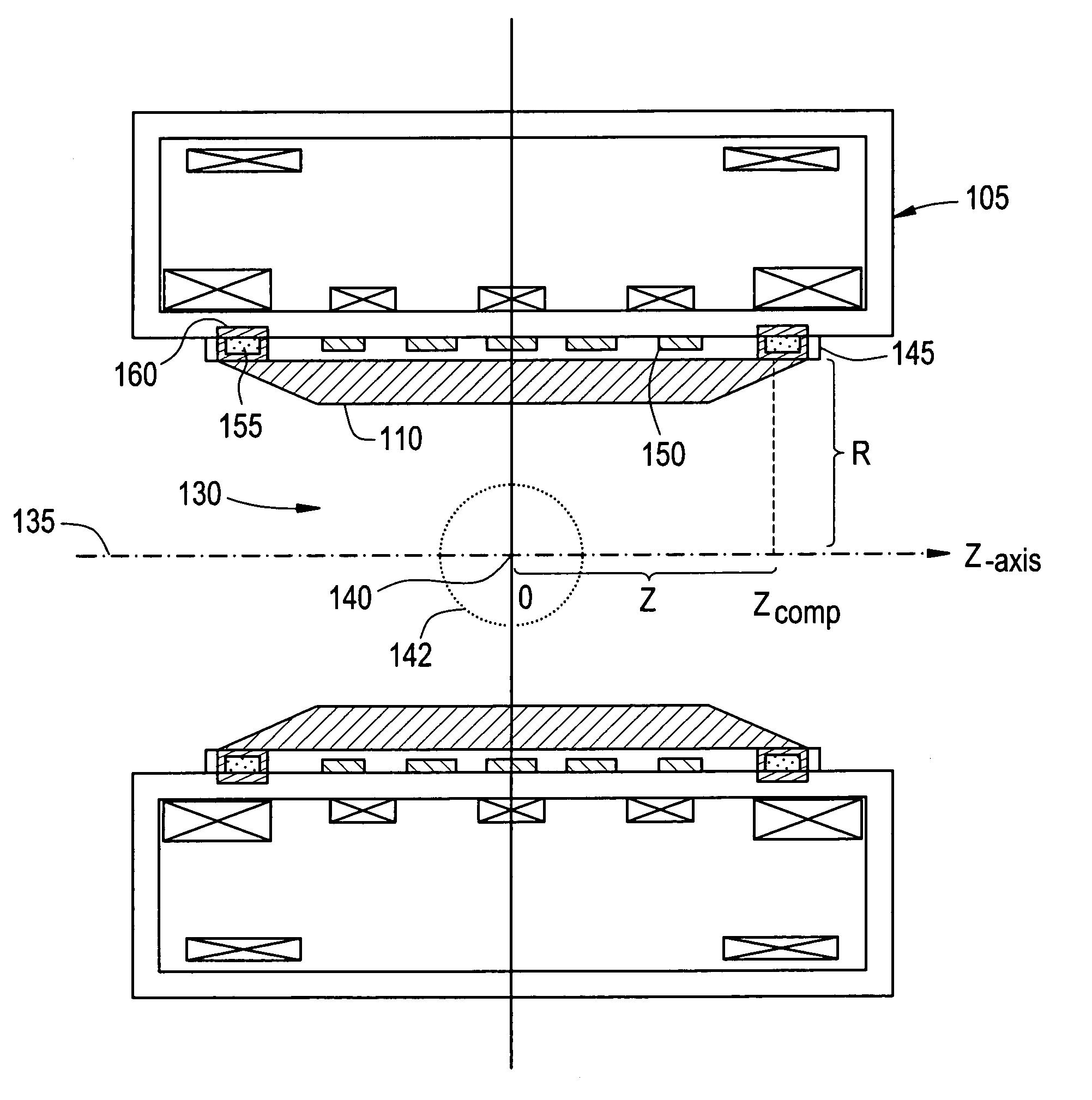
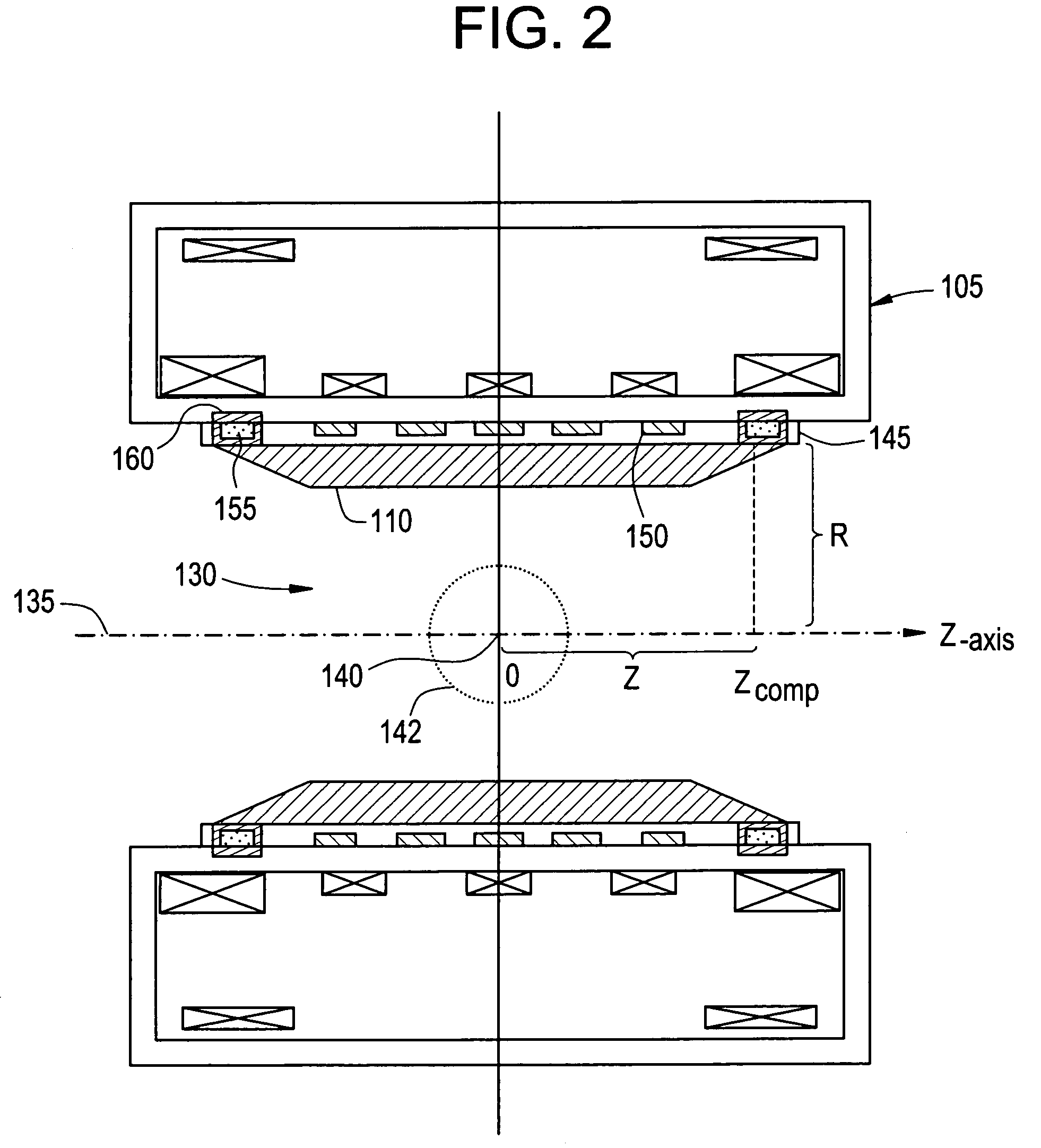
[0013]An embodiment of the invention provides a magnetic field generating apparatus for use in magnetic resonance imaging (MRI) having two sets of magnetic field adjusting shim elements. A first set of shim elements are configured to compensate for the inhomogeneities resulting from the main field generator, and a second set of shim elements are configured to compensate for the inhomogeneities resulting from a temperature change in the first set of shim elements. While embodiments described herein depict two sets of shim elements, it will be appreciated that the disclosed invention is not so limited and may also be applicable to multiple sets of shim elements, particularly with respect to the second set of shim elements.

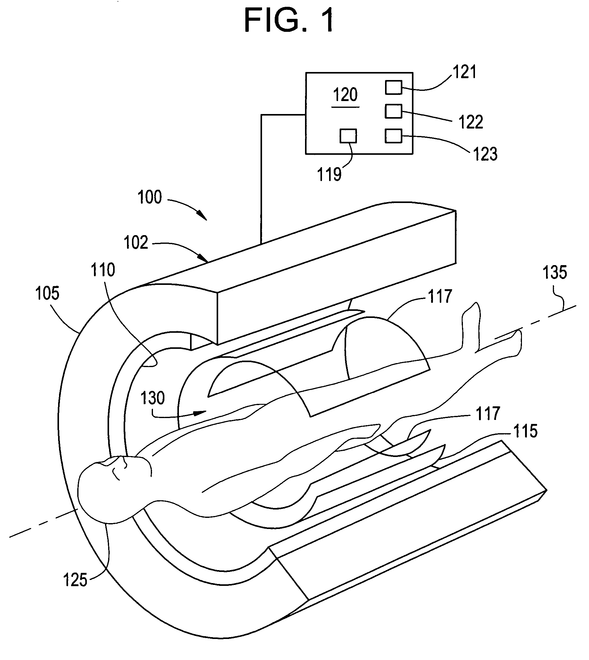
[0014]FIG. 1 depicts an exemplary embodiment of an MRI system 100 having a magnetic field generating apparatus 102 and a control system 120 for the control and operation thereof. An exemplary apparatus 102, shown having a portion cutaway to show structure within appa...


PUM


Abstract

A magnetic field generating apparatus for use in magnetic resonance imaging (MRI) is disclosed. The apparatus includes an annular magnet field generator defining a patient bore, a gradient coil disposed between the magnetic field generator and the patient bore, a first set of shim elements, and a second set of shim elements. The patient bore has an imaging volume, a z-axis, and an isocenter. The first set of shim elements are disposed at a region between the magnetic field generator and the imaging volume, and the second set of shim elements are disposed at the region at a location having equal to or greater than a specified Z / R ratio, where Z defines an axial distance from the isocenter and R defines a radial distance from the z-axis.

Description

BACKGROUND OF THE INVENTION[0001]The present disclosure relates generally to a magnetic field generating apparatus for magnetic resonance imaging, and particularly to a magnetic field generating apparatus with compensation of the variation of the central field.[0002]Magnetic resonance imaging (MRI) for medical diagnostics or otherwise requires a magnetic field generating apparatus capable of producing a high degree of final homogeneity in the magnetic field generated in the imaging volume. To accomplish this high degree of homogeneity, shimming systems are used, which often include passive shimming elements. Steel shim elements placed inside the patient bore and saturated by the main field provide a desirable degree of compensation to offset manufacturing and environmental inhomogeneities inherent in the MRI system. The total amount and location of the shimming steel varies from magnet to magnet, where large amounts of steel may be required in magnets with high original inhomogeneit...

Claims


Application Information

Patent Timeline
Patent Type & Authority Patents(United States)
IPC IPC(8): G01V3/00
CPCG01R33/3873
Inventor JARVIS, PETERLVOVSKY, YURI
Owner GENERAL ELECTRIC CO
Learn More