Thin-film magnetic head, head gimbal assembly, and hard disk drive incorporating a heater
a technology of thin film and heater, which is applied in the direction of mounting head within the housing, manufacturing head surface, instruments, etc., can solve the problem of hard to adjust the heating state of the heater member to a desirable sta
Active Publication Date: 2007-05-29
TDK CORPARATION
View PDF19 Cites 21 Cited by
- Summary
- Abstract
- Description
- Claims
- Application Information
AI Technical Summary
Benefits of technology
This approach allows for a controlled reduction in the gap between the thin-film magnetic head and the recording medium, enabling higher density storage while stabilizing the heating state and reducing fluctuations in ohmic value, thus improving the reliability and efficiency of the hard disk drive.
Problems solved by technology
When energizing the heater member, the electric resistivity of the heater member itself changes (increases) as the temperature of the heater member rises, thereby making it harder to adjust the heating state of the heater member to a desirable state.
Method used
View moreImage
Smart ImageViewing Examples
Examples
examples 1 to 12
and Examples 1 to 12;
[0035]FIG. 13 is a chart showing Examples 13 to 27; and
[0036]FIG. 14 is a chart showing Examples 28 to 42.
Login to View More PUM
| Property | Measurement | Unit |
|---|---|---|
| thickness | aaaaa | aaaaa |
| thickness | aaaaa | aaaaa |
| thickness | aaaaa | aaaaa |
Abstract
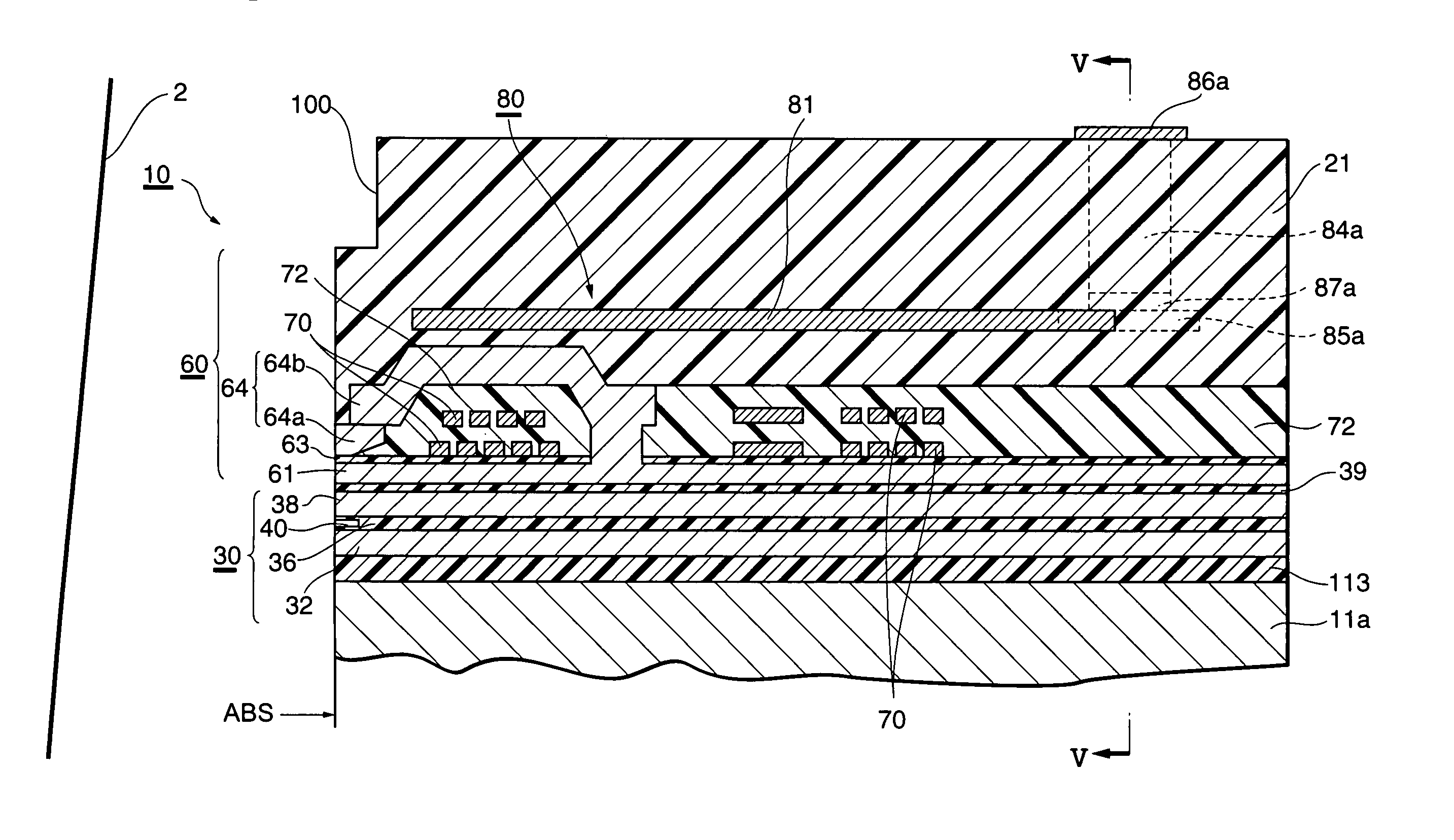
A thin-film magnetic head comprises at least one of an electromagnetic transducer and a magnetoresistive device, and a heater member adapted to generate heat upon energization. The heater member contains NiCu or NiCr.
Description
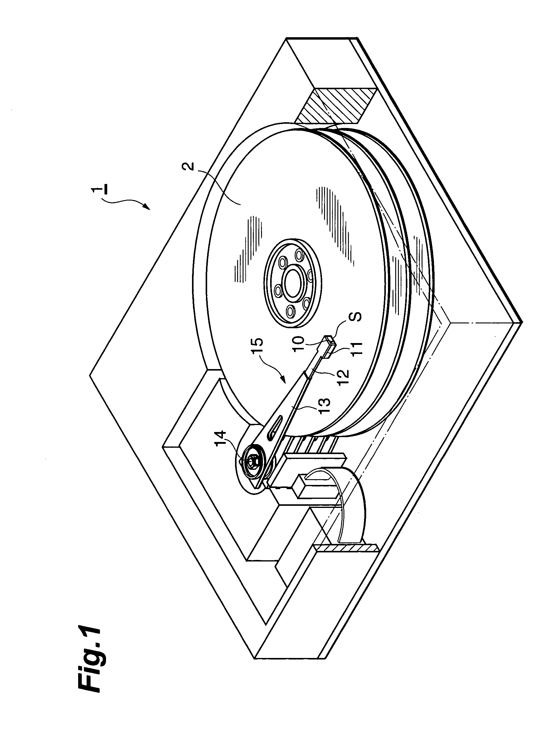
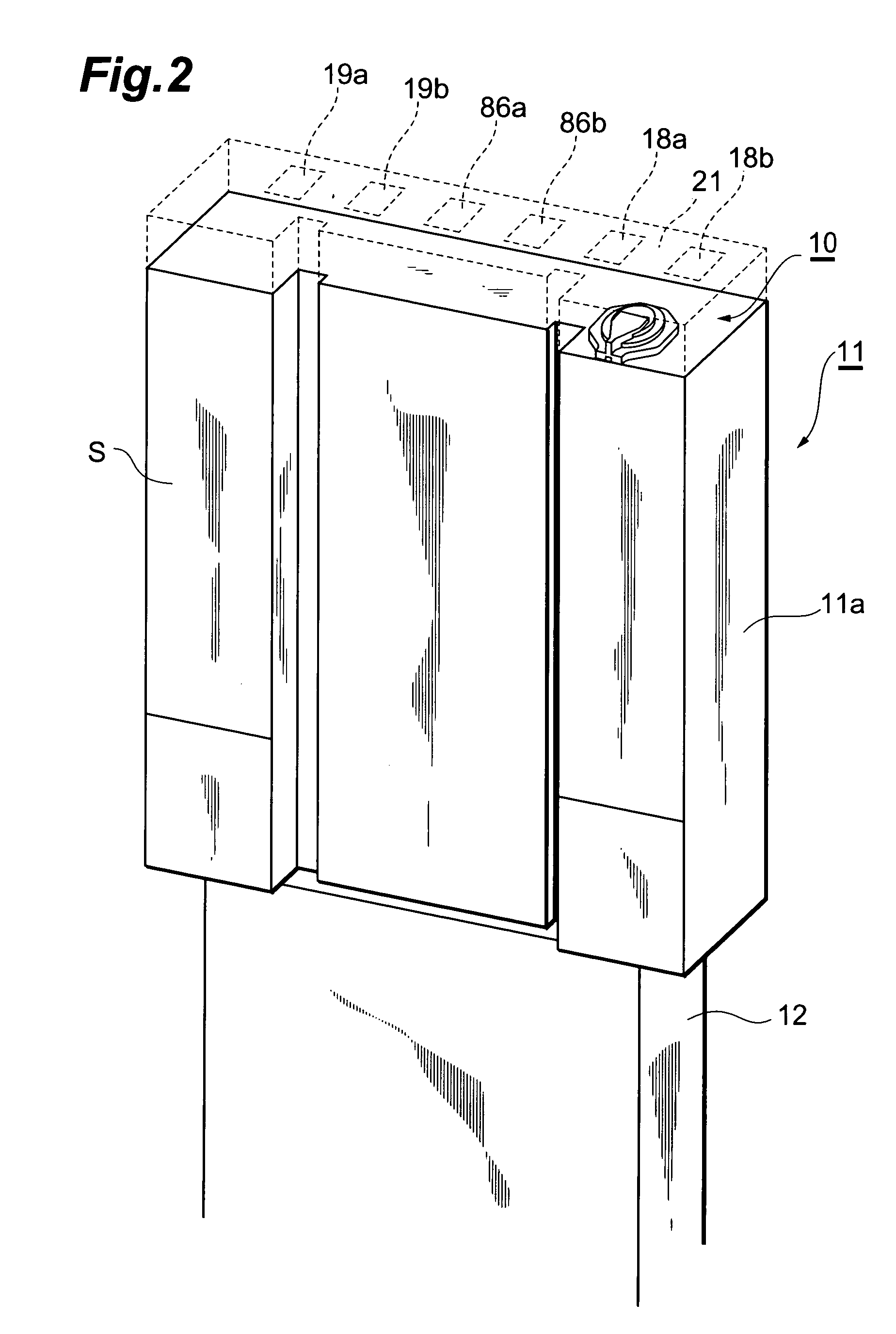
BACKGROUND OF THE INVENTION[0001]1. Field of the Invention[0002]The present invention relates to a thin-film magnetic head, a head gimbal assembly, and a hard disk drive.[0003]2. Related Background Art[0004]A thin-film magnetic head provided with an electromagnetic transducer for writing and a magnetoresistive device for reproducing is configured so as to float up from a hard disk, which is a recording medium, at the time of recording / reproducing with respect to a hard disk drive. Specifically, the thin-film magnetic head is mounted to a gimbal, which is attached to a leading end part of a flexible suspension arm, so as to construct a head gimbal assembly (HGA). As an airflow accompanying the rotation of the hard disk runs under the thin-film magnetic head, the suspension arm flexes, whereby the head floats up.[0005]As hard disks have been achieving a higher density, the gap between the thin-film magnetic head and a hard disk, i.e., the head flying height, has been decreasing from 2...
Claims
Login to View More Application Information
Patent Timeline
 Patent Type & Authority Patents(United States)
IPC IPC(8): G11B5/187G11B5/33G11B5/10G11B5/105G11B5/127G11B5/31G11B5/39G11B5/48G11B5/54G11B5/56G11B5/58
CPCG11B5/488G11B5/4886G11B5/54G11B5/56G11B5/58G11B5/6064G11B5/3103G11B5/3903G11B5/10G11B5/105
Inventor SASAKI, TETSUROOYAMA, NUBUYAOMATA, EIICHISANO, MASASHIKOIDE, SOJI
Owner TDK CORPARATION
Features
- R&D
- Intellectual Property
- Life Sciences
- Materials
- Tech Scout
- Unparalleled Data Quality
- Higher Quality Content
- 60% Fewer Hallucinations
Learn More Browse by: Latest US Patents, China's latest patents, Technical Efficacy Thesaurus, Application Domain, Technology Topic, Popular Technical Reports.
© 2025 PatSnap. All rights reserved.Legal|Privacy policy|Modern Slavery Act Transparency Statement|Sitemap|About US| Contact US: help@patsnap.com


