
Digital video broadcasting

a digital video and broadcasting technology, applied in the field of digital video broadcasting, can solve the problems of large data loss, high distortion of video images of at least some programs, spatial and temporal, etc., and achieve the effects of avoiding quantization noise, increasing potential compression, and great flexibility in scheduling

Inactive Publication Date: 2007-05-29
SCREENPEAKS
View PDF40 Cites 45 Cited by
  • Summary
  • Abstract
  • Description
  • Claims
  • Application Information

AI Technical Summary

Benefits of technology

[0013]As a result of the method of the invention, the encoding of all VICs is highly efficient, so that a large number of VICs can be combined into a single channel with minimal noticeable image distortions. The meaning of this is that the method and apparatus of the invention enable a plurality of informational video programs to be transmitted as a single digital video transport stream, of a given rate, so that the resultant displayed video images (including their time dimension) of any program will appear to normal users essentially similarly to those that would be obtained by encoding the respective program according to conventional methods and transmitting it alone over a similar transport stream. A complementary aspect of this meaning is that if the same plurality of programs were encoded and multiplexed into a similar transport stream by conventional methods, the resultant video images for at least some of the programs would be highly distorted, spatially and temporally—reflecting considerable loss of data.
[0055]adjusting portion of the respective encoded video stream so as to reduce the amount of data in the portion;

Problems solved by technology

A complementary aspect of this meaning is that if the same plurality of programs were encoded and multiplexed into a similar transport stream by conventional methods, the resultant video images for at least some of the programs would be highly distorted, spatially and temporally—reflecting considerable loss of data.

Method used


Image

  • Digital video broadcasting
  • Digital video broadcasting
  • Digital video broadcasting

Examples


Embodiment Construction

[0065]The method and apparatus of the present invention will be described hereunder in the context of a typical head-end of a digital video cable system. This is done by way of illustrative example and not to limit the scope of the invention. Application of the invention to other digital video broadcast systems should be possible with minor modifications, obvious to practitioners of the art.

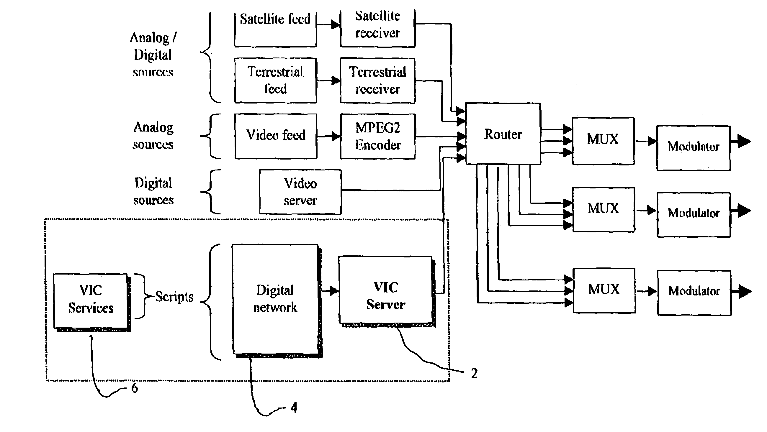
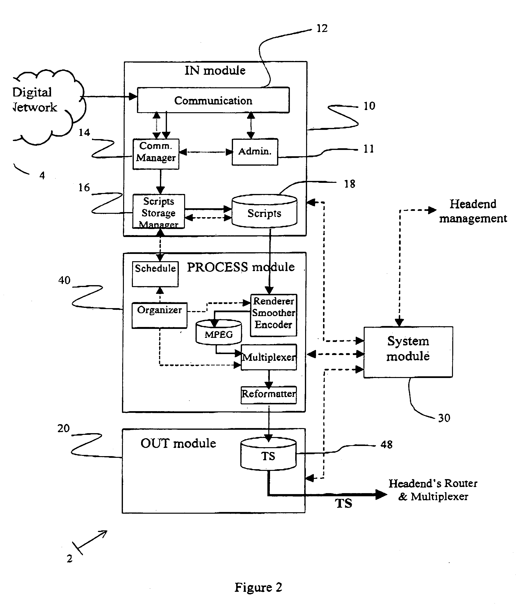
[0066]FIG. 1 shows schematically a VIC Server 2 (within the shaded area), which embodies the present invention, connected to the router of the exemplary head-end of a digital cable system, to input a transport stream thereto, alongside conventional inputs as discussed in the Background section above. FIG. 2 shows an overall block diagram of a preferred embodiment of VIC Server 2 according to the present invention. It consists largely of an Input module 10, a Process module (PM) 40, an Output module 20 and a System Controller 30.

[0067]Input module 10 of VIC Server 2 communicates with all sources o...


PUM


Abstract

A method is provided for transmitting a plurality of informational video programs over a single digital transport stream to a plurality of receivers, wherein the receivers are operative to select from the transport stream data identified with any given program and to decode the identified data into a displayable video signal. The method consists of storing a plurality of the informational video programs, scheduling them along corresponding simultaneous time lines, rendering each program and encoding, according to standards, into a video stream, multiplexing the video streams in an interleaved manner, and formatting them to become the transport stream, wherein any of the operations of scheduling, rendering encoding and multiplexing are such that images, obtained by decoding transmitted data identified with any of the programs and displaying the resultant video signal, are essentially similar to those obtainable by rendering and encoding the programs separately, transmitting the respective encoded program alone over a similar transmission stream, decoding the transmitted data and displaying the resultant video signal.

Description

[0001]This application claims benefit of U.S. provisional application No. 60 / 239,452, filed Oct. 11, 2000.FIELD OF THE INVENTION[0002]This invention relates to Digital Video Broadcasting (DVB) and, in particular, to the efficient broadcasting of informational channels over a DVB system.BACKGROUND OF THE INVENTION[0003]Digital Video Broadcasting systems have been defined in terms of standards for a variety of broadcasting media, such as cable and direct satellite broadcasting, and for most stages of the broadcasting chain, from contents origination to decoding at the viewer's television set. Such systems are now in the early stages of adoption.[0004]Typically, a DVB system, such as that using cables for signal distribution, broadcasts a plurality of contents channels (also referred to hereunder as channels) and consists of a head-end, the cable distribution system and a decoder (such as in a set-top box) associated with a television receiver at each subscriber location. At the head-e...

Claims


Application Information

Patent Timeline
Patent Type & Authority Patents(United States)
IPC IPC(8): G06K9/36G06K9/46H04N21/2343H04N21/2365H04N21/24H04N21/262H04N21/2662H04N21/2665H04N21/434
CPCH04N21/23614H04N21/2365H04N21/4347H04N21/4348H04N21/2343H04N21/2402H04N21/262H04N21/2662H04N21/2665
Inventor OLSHANSKY, AVIGDORCASPI, YORAM
Owner SCREENPEAKS
Learn More