Apparatus and method for image coding and decoding

a technology of image coding and decoding, applied in the field of image coding apparatus and method, can solve problems such as mismatch in the relationship between video streams

Inactive Publication Date: 2007-05-29
SONY CORP
View PDF6 Cites 53 Cited by
  • Summary
  • Abstract
  • Description
  • Claims
  • Application Information

AI Technical Summary

Benefits of technology

[0013]It is therefore an object of the present invention to provide an image coding apparatus and method, an image decoding apparatus and method, and a recording medium, wherein there is no mismatch of information caused in the relationship between a video stream after re-encoding and other data is generated and recorded on the recording side and reproduction on the reproducing side. For example, a smaller picture frame is prevented from occurring on the reproducing side by referencing the information generated on the recording side.
[0069]As described and according to the image decoding apparatus and method and the program stored in the third recording medium, when a video stream is separated from an input multiplexed stream, the separated video stream is decoded, and the decoded video stream is displayed on the basis of multimedia coding data, a mismatch occurs. On the basis of the additional information about this mismatch occurrence, a predetermined conversion process is performed on the decoded video stream. This novel configuration prevents the mismatch from occurring between the video stream and the multimedia coding data.

Problems solved by technology

However, this approach presents a problem of causing a mismatch in the relationship between the video stream resulting from re-encoding and the multimedia coding data.

Method used


Image

  • Apparatus and method for image coding and decoding
  • Apparatus and method for image coding and decoding
  • Apparatus and method for image coding and decoding

Examples


Embodiment Construction

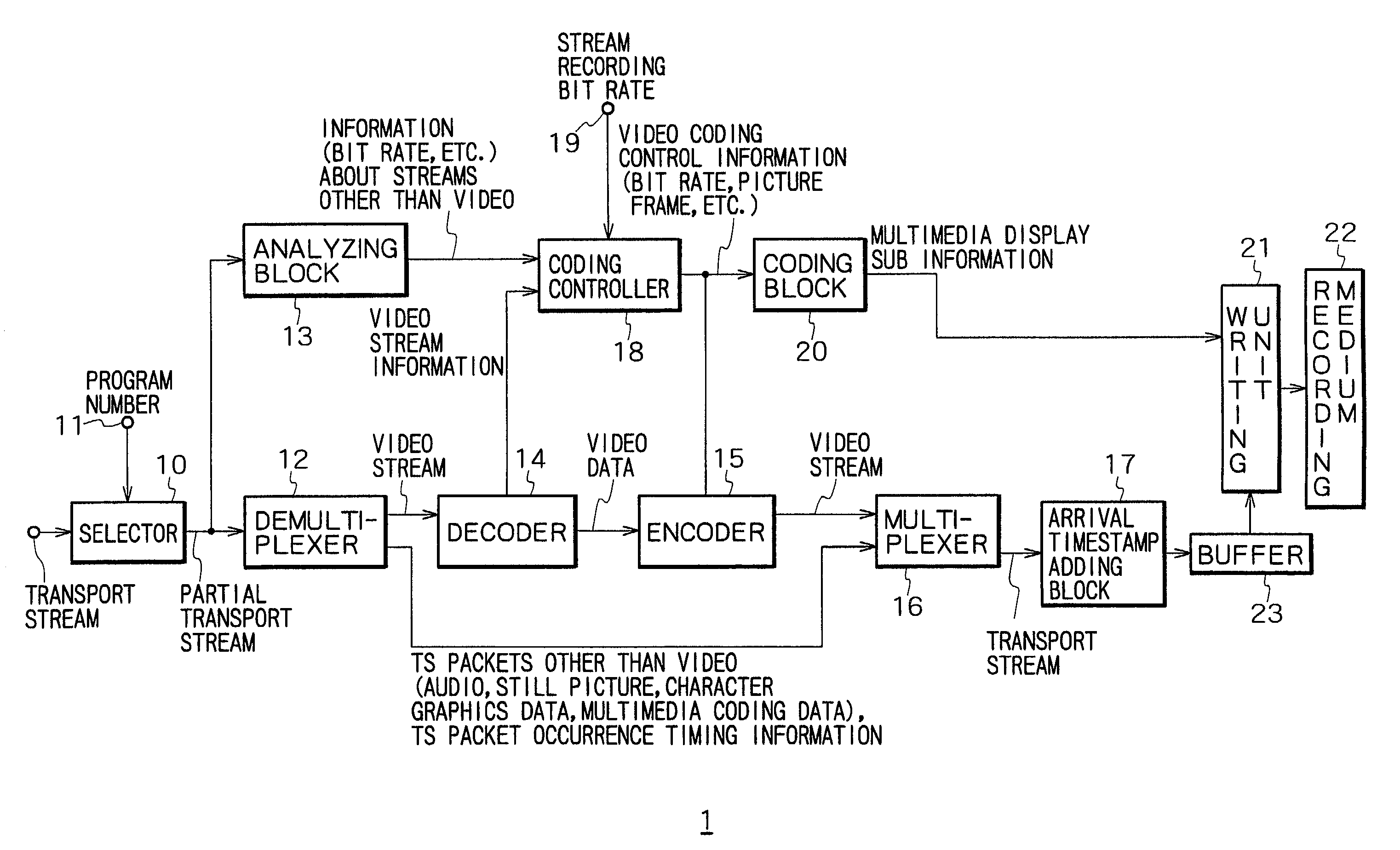
[0099]This invention will be described in further detail by way of example with reference to the accompanying drawings. Now, referring to FIG. 3, there is shown a block diagram illustrating an exemplary configuration of a recording apparatus 1 practiced as one embodiment of the invention. A transport stream received at an antenna, not shown, is input in a selector 10. A program number (a channel number) specified by the user is also input from a terminal 11 to the selector 10. Referring to the received program number, the selector 10 extracts the specified program from the received transport stream and outputs a partial transport stream. The partial transport stream is input in a demultiplexer 12 and an analyzing block 13.

[0100]The partial transport stream input in the demultiplexer 12 is separated into a video stream and other streams (audio, still picture, character graphics, and multimedia coding data for example). The video stream thus obtained is output to a decoder 14. The oth...


PUM


Abstract

This invention is intended to prevent a mismatch from occurring between a re-encoded and recorded video stream and other data. A transport stream is input to a recording apparatus and is then supplied to a demultiplexer and an analyzing block. The analyzing block outputs non-video stream information to a coding controller. The coding controller controls the encoding operation of an encoder on the basis of the input information and outputs video coding control information to a coding block. On the basis of video coding control information, the coding block generates multimedia display sub-information (including information about a picture frame, for example) which prevents a mismatch from occurring on the reproducing side between video and other data, and outputs this information to a writing block. The writing block records the video stream and other data to a recording medium, as well as recording the multimedia display sub-information generated by the coding block.

Description

CROSS-REFERENCE TO RELATED APPLICATIONS[0001]The present application claims priority from Japanese Application Nos. P2000-165298 filed Jun. 2, 2000 and P2001-001031 filed Jan. 9, 2001, the disclosures of which are hereby incorporated by reference herein.BACKGROUND OF THE INVENTION[0002]The present invention relates generally to an image coding apparatus and method, an image decoding apparatus and method, and a recording medium. More specifically, the present invention relates to an image coding apparatus and method, an image decoding apparatus and method, and a recording medium which are suitable for use in apparatus for re-encoding video streams and recording and reproducing the re-encoded video streams.[0003]Digital television broadcasts such as European DVB (Digital Video Broadcast), American DTV (Digital Television) broadcast, and Japanese BS (Broadcast Satellite) digital broadcast use MPEG (Motion Picture Expert Group) 2 transport streams. A transport stream consists of continu...

Claims


Application Information

Patent Timeline
Patent Type & Authority Patents(United States)
IPC IPC(8): H04N7/26H04N19/40H04N5/00H04N5/781H04N5/85H04N5/907H04N5/91H04N7/173H04N7/24H04N7/50H04N9/804H04N9/82H04N19/00H04N19/115H04N19/134H04N19/172H04N19/25H04N19/46H04N19/70H04N21/2343H04N21/2362H04N21/44H04N21/6332
CPCH04N19/188H04N9/8205H04N21/23614H04N21/40H04N21/4334H04N21/4341H04N21/4348H04N21/440263H04N21/6332H04N21/6373H04N21/6377H04N21/654H04N21/658H04N19/70H04N19/172H04N19/46H04N19/149H04N19/115H04N19/146H04N19/162H04N19/177H04N19/44H04N19/40H04N19/59H04N7/0122H04N5/781H04N9/8042H04N9/8227H04N9/8233H04N5/91
Inventor KATO, MOTOKI
Owner SONY CORP
Why Eureka
Try Eureka