Recirculation bubbler for glass melter apparatus

a technology of glass melter and bubbler, which is applied in the field of molten glass recirculating apparatus and systems, can solve the problems of liquid flow velocity loss in localized liquid recirculation, and achieve the effect of efficient distribution and minimal energy loss

Inactive Publication Date: 2007-06-05
THE UNITED STATES AS REPRESENTED BY THE DEPARTMENT OF ENERGY
View PDF6 Cites 8 Cited by
  • Summary
  • Abstract
  • Description
  • Claims
  • Application Information

AI Technical Summary

Benefits of technology

[0008]Generally speaking, the glass recirculation bubbler of the invention overcomes a common disadvantage of prior art bubblers by constraining the induced liquid flow so as to take place in the upward direction, and, quite importantly, does this with minimal energy loss. As will appear from the discussion below, an important feature of the invention concerns the provision of a gas bubble distribution device as part of the bubbler so as to ensure that bubbles of the desired size are produced and are efficiently distributed within the constrained flow.

Problems solved by technology

A disadvantage of such air bubbles is that liquid flow velocities imparted by the bubbles are lost in the localized liquid recirculation.

Method used


Image

  • Recirculation bubbler for glass melter apparatus
  • Recirculation bubbler for glass melter apparatus
  • Recirculation bubbler for glass melter apparatus

Examples


Embodiment Construction

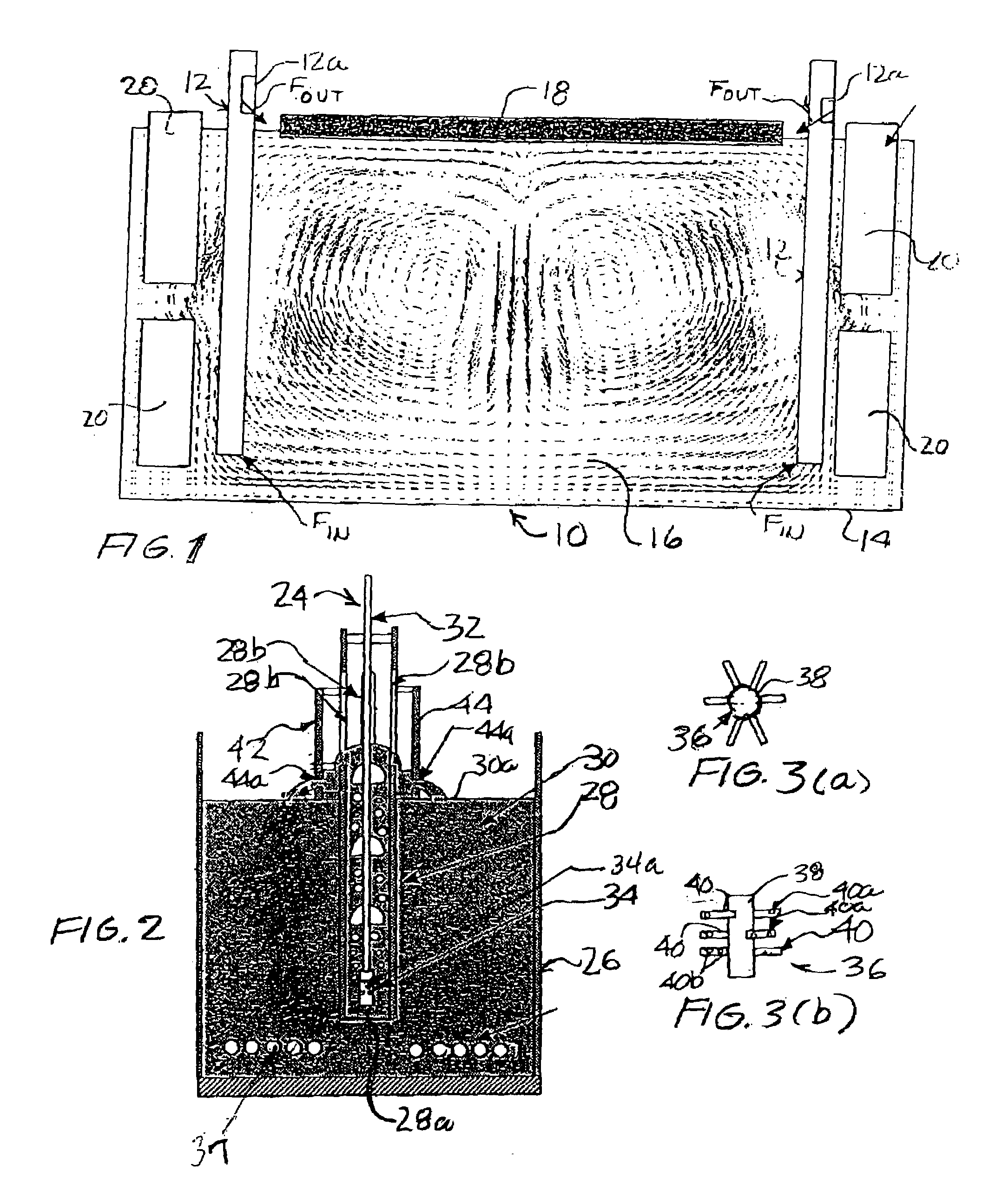
[0027]Referring to FIG. 1, there is shown a glass melter 10 incorporating a pair of gas bubblers 12 constructed in accordance with the invention. The melter or melting apparatus 10 includes a tank or container 14 in which a bath or pool 16 of molten glass is contained. A cold cap is indicated at 18 while electrodes are indicated at 20. It will be understood that melter 10 is conventional apart from bubblers 12, and that a bubbler, or bubblers, in accordance with the invention can be incorporated in other, different melters.

[0028]As illustrated by arrows Fin and Fout, the molten glass in bath 16 flows into the bottom of the bubblers 12 and flows out of the bubblers 12 through openings therein located above the upper surface of the molten glass, and, in FIG. 1, through openings 12a near the top of the bubblers 12, so as to create the flow pattern shown. This flow pattern is discussed in more detail below.

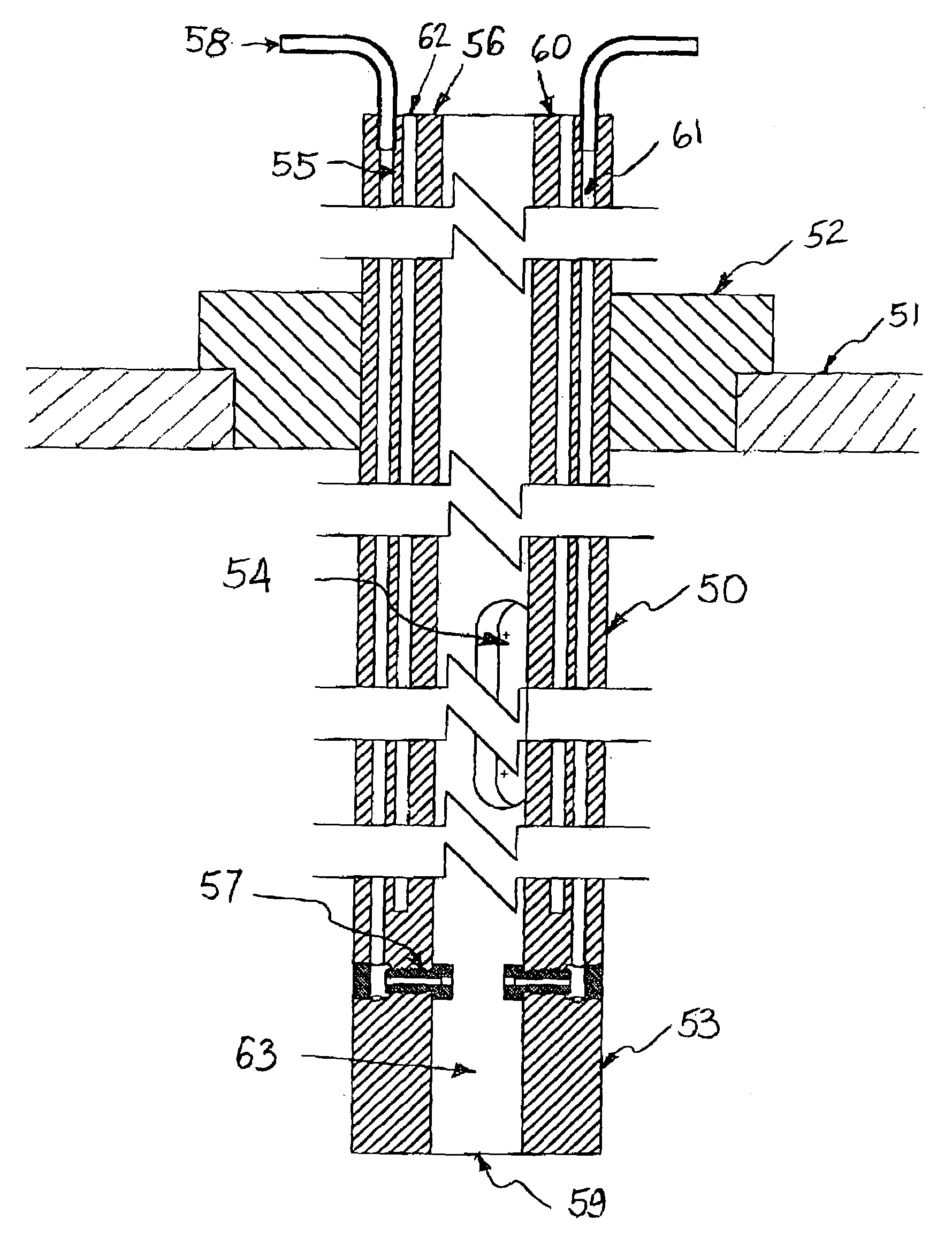
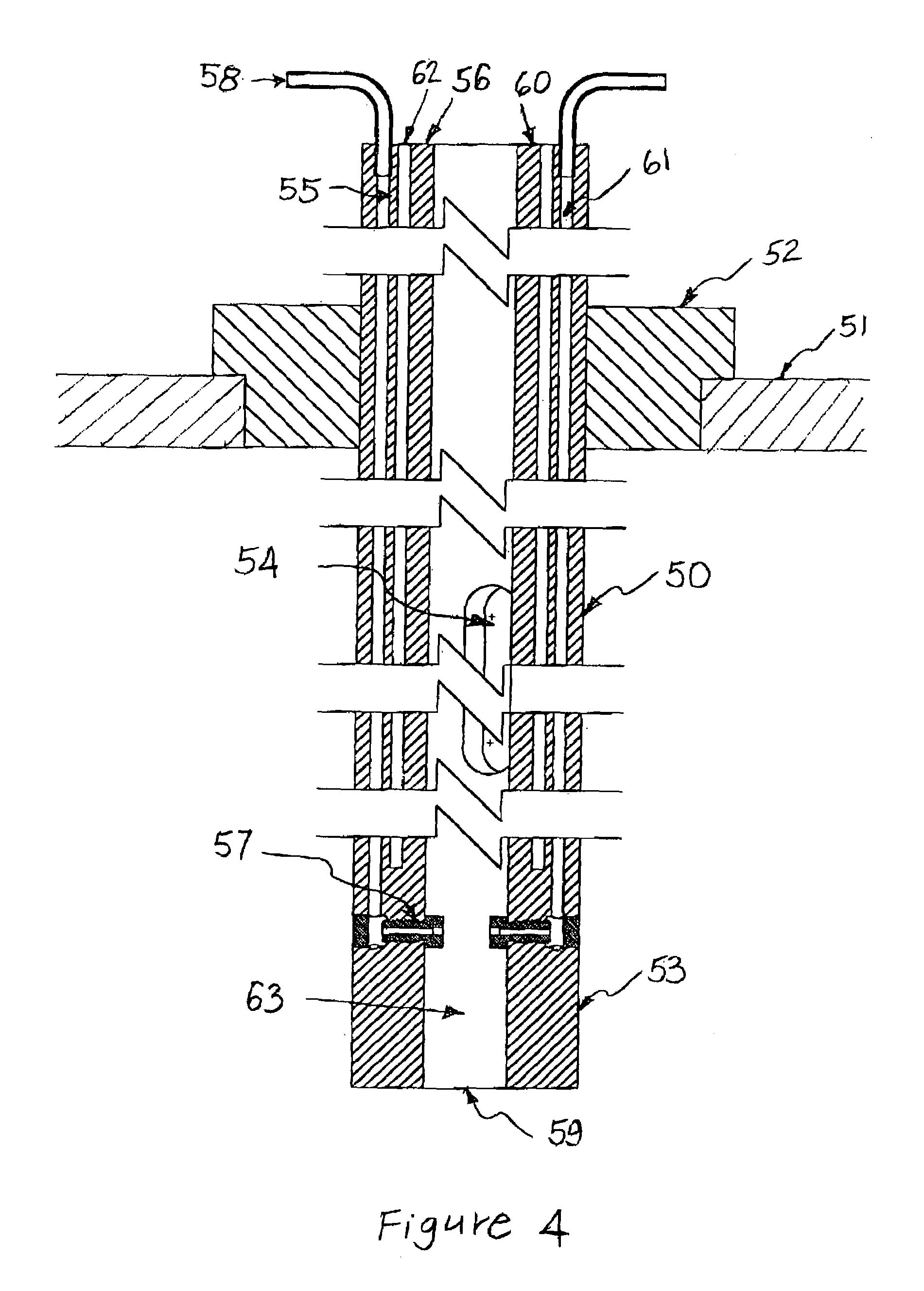
[0029]Referring to FIG. 2, a schematic showing is provided of a simplified bubble...


PUM

PropertyMeasurementUnit
diameteraaaaaaaaaa
anglesaaaaaaaaaa
flow velocitiesaaaaaaaaaa

Abstract

A gas bubbler device provides enhanced recirculation of molten glass within a glass melter apparatus. The bubbler device includes a tube member disposed within a pool of molten glass contained in the melter. The tube member includes a lower opening through which the molten glass enters and upper slots disposed close to (above or below) the upper surface of the pool of molten glass and from which the glass exits. A gas (air) line is disposed within the tube member and extends longitudinally thereof. A gas bubble distribution device, which is located adjacent to the lower end of the tube member and is connected to the lower end of the gas line, releases gas through openings therein so as to produce gas bubbles of a desired size in the molten glass and in a distributed pattern across the tube member.

Description

[0001]The United States Government has rights in this invention pursuant to a contract between the United States Department of Energy and Westinghouse Savannah River Company.BACKGROUND[0002]1. Field of the Invention[0003]The invention relates to molten glass recirculating apparatus and systems and, more particularly, to a bubbler apparatus for a glass melter that provides enhanced glass recirculation.[0004]2. Description of the Related Art[0005]Air bubblers have previously been used in glass melters. In general, these bubblers comprise air tubes for injecting air bubbles into the free glass pools. A disadvantage of such air bubbles is that liquid flow velocities imparted by the bubbles are lost in the localized liquid recirculation. The need to provide recirculation and agitation of molten glass is well documented and a number of issued patents relate to this problem. Considering some of these patents, U.S. Pat. No. 6,334,337 to Macedo et al. relates to an air bubbler for increasing...

Claims


Application Information

Patent Timeline
Patent Type & Authority Patents(United States)
IPC IPC(8): C03B5/193C03B5/04
CPCB01F13/0222B01F13/0244B01F13/0283C03B5/193B01F33/40511B01F33/403B01F33/409
Inventor GUERRERO, HECTORBICKFORD, DENNIS
Owner THE UNITED STATES AS REPRESENTED BY THE DEPARTMENT OF ENERGY
Why Eureka
Try Eureka