Container for storing an implantable medical device and a method for packaging such a device

a technology for medical devices and containers, applied in the direction of containers, tray containers, diagnostics, etc., can solve the problems of uncomplicated and inexpensive solutions, and achieve the effect of improving the reception and transmission properties of such devices

Active Publication Date: 2013-06-04
ST JUDE MEDICAL
View PDF22 Cites 4 Cited by
  • Summary
  • Abstract
  • Description
  • Claims
  • Application Information

AI Technical Summary

Benefits of technology

[0011]The above object is achieved in accordance with the present invention by an apparatus that includes an implantable medical device and a container for the implantable medical device prior to implantation, wherein the container has an impedance altering substance located therein in proximity to the antenna of the implantable medical device in the container, the impedance altering substance passively altering the input impedance of the antenna to improve the reception and transmission properties thereof while the implantable medical device is in the container.
[0014]In order to match the antenna to the radio and the transmission line of an IMD, tuning using tunable reactive components is possible and widens the usable spectrum of antenna impedances. However, the great difference between the environment of body tissue, where the IMD is implanted, and the environment of a shipping container, where the IMP is stored prior to implantation, would necessitate a very big tuning capability to handle this load. The present invention is based on the insight that a more viable way is to manipulate the input impedance of the antenna when the IMD is stored in the shipping container. By altering the electrical material properties of the storage packaging in the surroundings of the implantable medical device in accordance with the present invention, such that the input impedance of the antenna is adjusted to improve receive and transmit properties of the antenna when the implantable medical device is stored by the storage packaging, an effective improvement of the telemetry communication between an external device and the IMD is attained. This solution is uncomplicated and inexpensive. Since this solution does not require a capacitive or direct electrical coupling between the IMD and any external equipment in order to improve the efficiency of the antenna, the risk of interruption of such a coupling is eliminated.
[0015]The present invention makes it possible to efficiently communicate with the IMD while stored in a shipping container via radio frequency communication over larger distances. This enables a user to make an inventory of the IMDs in stock by means of an external radio frequency communication device, e.g., an inventory of the amount of IMDs, types of IMDs etc. The present invention also makes it possible for the user to execute testing procedures while the IMD is stored in the shipping container and while being in stock (inventory), or to verify or customize initial programmable parameter values before the IMD is implanted.
[0020]The antenna of the IMD can be located in the housing of the IMD containing the device circuitry, in or on the plastic header of the IMD used to interconnect the IMD to electrical leads, mounted to the IMD housing, or incorporated as a portion of one of the leads. According to an advantageous embodiment of the apparatus according to the present invention, the member is positioned in the close surroundings of the antenna of the IMD, which efficiently influences the input impedance of the antenna more, and advantageously, the member extends along a substantial portion of the length of the antenna, which provides an even more effective influence on the input impedance of the antenna. The member can abut the IMD or be position with a small distance to the IMD. Advantageously, the member should not enclose too much of the antenna in order to avoid attenuation of the electromagnetic waves to and from the antenna.
[0021]Advantageously, the member of the apparatus of the present invention contains dielectric material in which conduction of electric current does not take place or is negligible, and in which an electric field can be maintained with a minimum loss of energy. Examples of dielectric materials are porcelain, ceramics, glass, and polymers. The member can have several different designs. The member can be in the form of a bag filled with a fluid and / or an amount of solids. The bag can for example be made of a polymeric material and be filled with any kind of fluid, such as a liquid or gel, or filled with an amount of solids made of ceramics, e.g. The member can also be in the form of one solid, e.g., made of ceramics. Advantageously, the dielectric constant of the member material is above 10. Further advantageously, the dielectric constant of the member material is between 10 and 60, preferably between 30 and 40. Advantageously, the conductivity of the member material is also set to efficiently influence the input impedance of the antenna.

Problems solved by technology

This solution is uncomplicated and inexpensive.

Method used


Image

  • Container for storing an implantable medical device and a method for packaging such a device
  • Container for storing an implantable medical device and a method for packaging such a device
  • Container for storing an implantable medical device and a method for packaging such a device

Examples


first embodiment

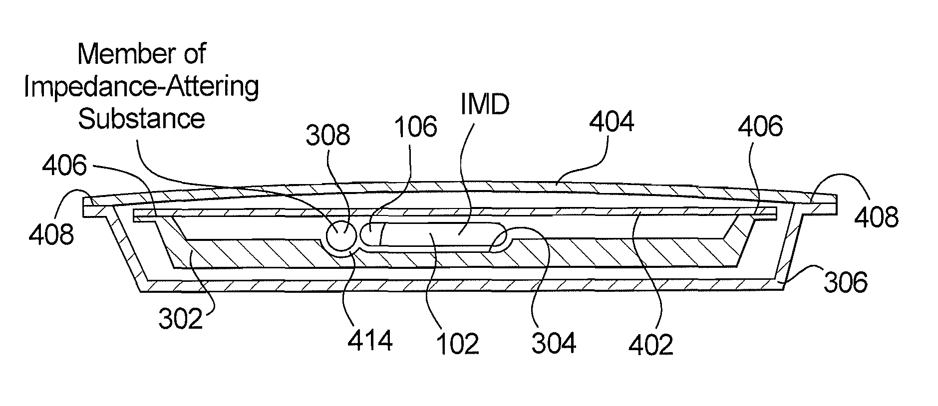
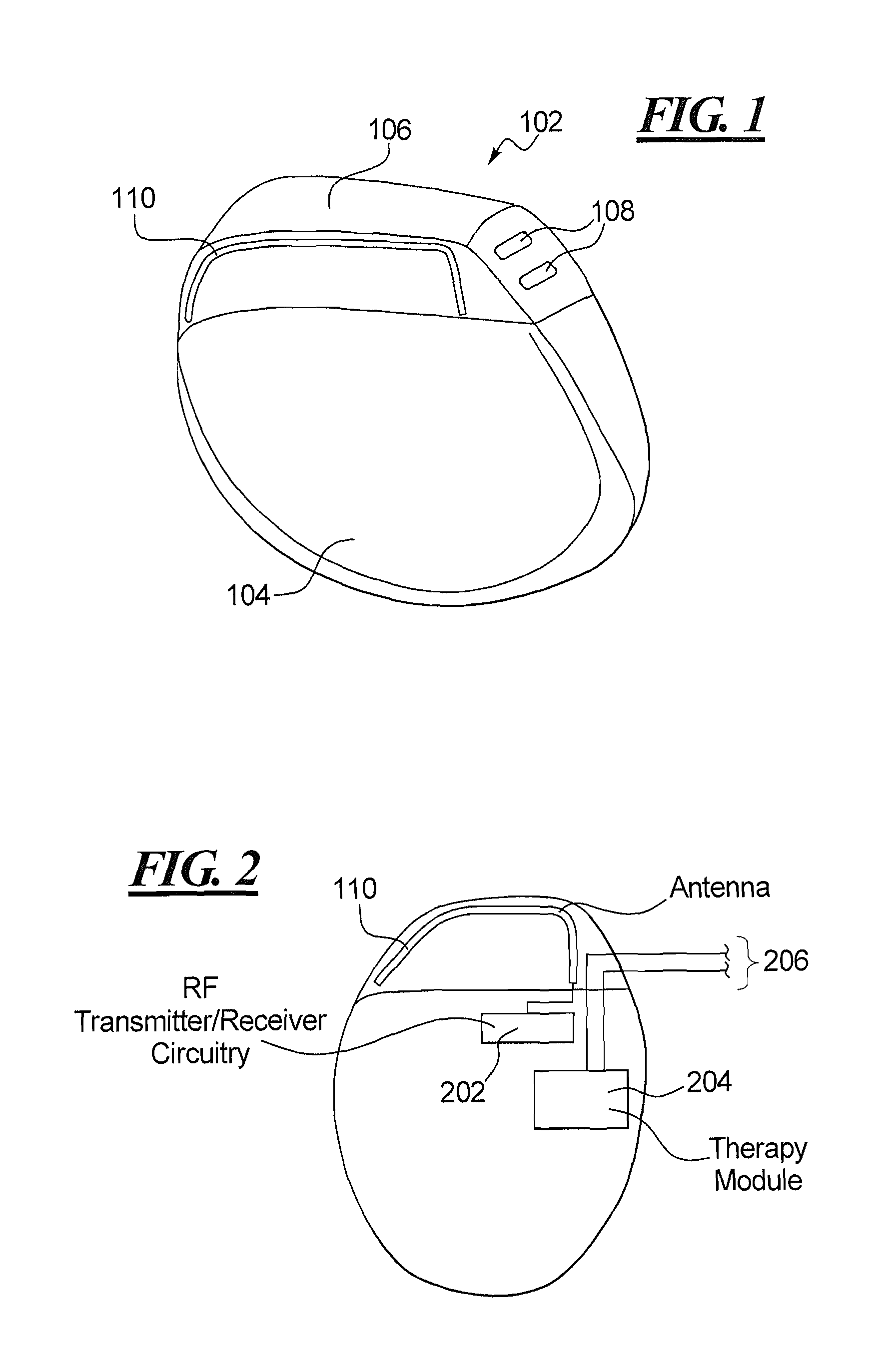
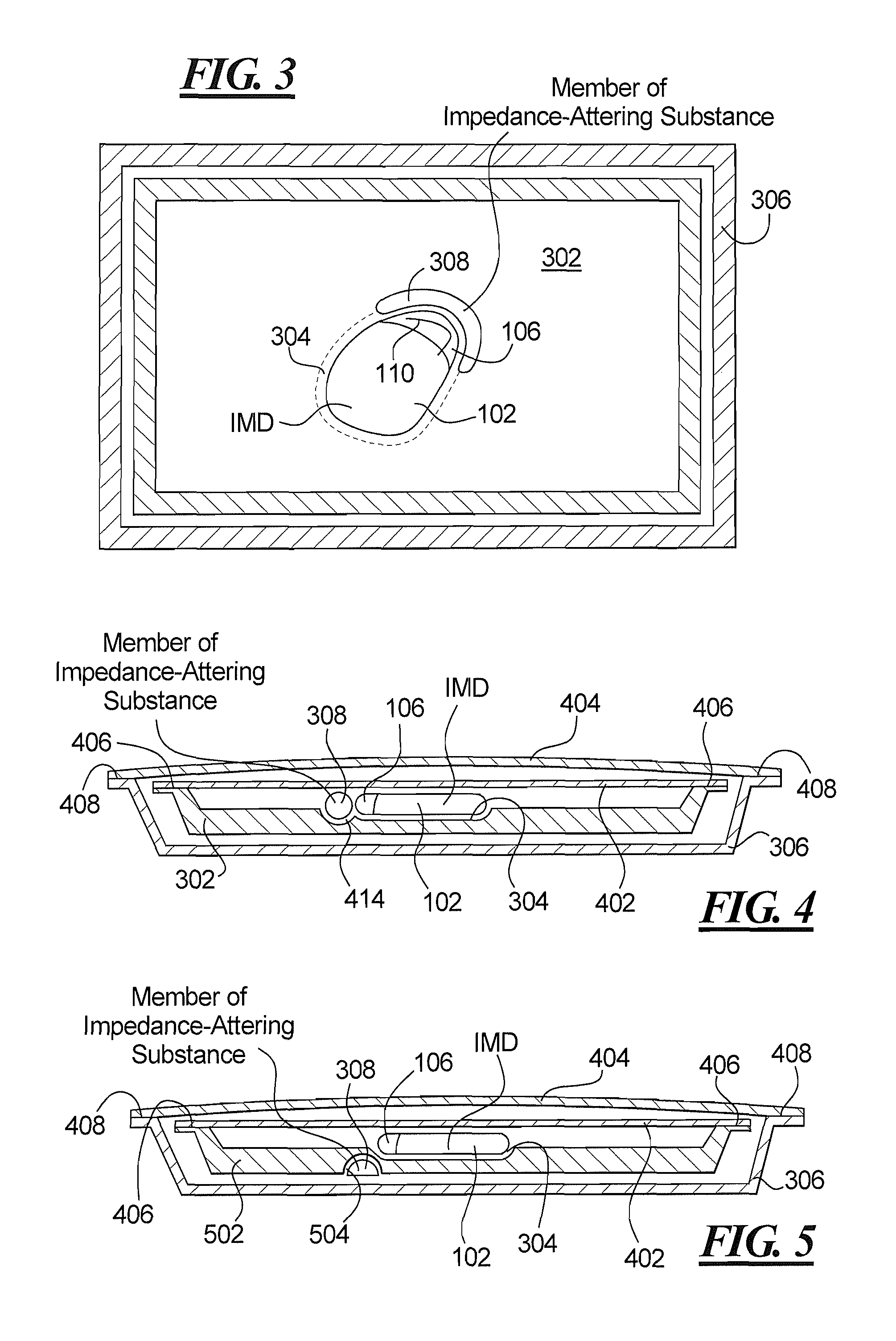
[0035]FIG. 3 shows a top view of the apparatus according to the invention. The apparatus comprises an IMD 102 as shown in FIGS. 1 and 2, and a container for storing the IMD 102 prior to implantation in body tissue. The container has a first sealable packaging tray 302 for housing the IMD 102, which first packaging tray 302 has a support in the form of a recess 304 for receiving and supporting the IMD 102. Further, the container has a second sealable packaging tray 306 for housing the first packaging tray 302. The trays 302, 306 are made of a suitable material, such as a rigid plastic material. The seals of the first and second packaging trays 302, 306 are excluded in FIG. 3. The apparatus includes an impedance altering substance in the form of one member 308 positioned in proximity to the IMD 102, when stored in the container, and in proximity to the recess 304. More precisely, the member 308 is positioned in the close surroundings of the antenna 110 and the recess 304 has such a co...

second embodiment

[0037]FIG. 5 is a cross-sectional side view of the apparatus according to the present invention, comprising an IMD 102 and a member 308 corresponding to the IMD 102 and the member 308 of the embodiment of FIGS. 3 and 4, but with a different container. Here, the inner packaging tray 502 is provided an external compartment 504 for receiving and retaining the member 308, and the member 308 is thus positioned on the outside of the inner packaging tray 502. This position of the member 308 is advantageous if the member 308 is formed by a bag with gel or liquid. In case the bag is damaged during storage and gel leaves the bag, the gel will not contaminate the IMD 102.

third embodiment

[0038]FIG. 6 is a cross-sectional side view of the apparatus according to the present invention, including an IMD 102 and a member 308 corresponding to the IMD 102 and the member 308 of the embodiment of FIGS. 3 and 4, but with a different container. In this embodiment, the outer packaging tray 602 is provided with an external compartment 604 for receiving and retaining the member 308, and the member 308 is thus positioned on the outside of the outer packaging tray 602. The inner packaging tray 606 is provided with a compartment 608 for receiving the external compartment 604 of the outer packaging tray 602, such that the member 308 is positioned in close proximity to the header 106 of the stored IMD 102. This position of the member 308 is advantageous if the member 308 is formed as a bag with gel or liquid. In case the bag is damaged during storage and gel leaves the bag, the gel will not contaminate the sterilized environment on the inside of the outer packaging tray 602, and thus ...


PUM


Abstract

An implantable medical device is stored in a container prior to implantation in body tissue. The IMD includes transmitter / receiver circuitry and at least one antenna. The storage container (packaging) includes an impedance altering substance positioned in proximity to the IMD when stored in the container, the substance having electrical material properties that alter the input impedance of the antenna to improve the reception and transmission properties of the antenna when the IMD is stored in the container. A container for storing an IMD having an antenna has a packaging tray for housing the IMD, the packaging tray having a support for supporting the IMD and the container including a substance positioned in proximity to the support that has electrical material properties that after the input impedance of the antenna of the IMD supported by the support, so as to improve the reception and transmission properties of the antenna. A method for packaging an IMD prior to implantation in body tissue includes the step of providing such an impedance altering substance in the pre-implantation IMD packaging, in proximity to the packaged IMD.

Description

BACKGROUND OF THE INVENTION[0001]1. Field of the Invention[0002]The present invention relates to a system for improving the communication with an implantable medical device while being stored prior to implantation in body tissue. The present invention also relates to an apparatus comprising an implantable medical device and a container for storing the implantable medical device prior to implantation in body tissue. Further, the present invention relates to a container for storing an implantable medical device. Finally, the present invention relates to a method for packaging an implantable medical device prior to implantation in body tissue.[0003]2. Description of the Prior Art[0004]In the context of implantable medical devices, IMDs, it is common to provide a communication link between the implanted IMD and an external device, such as a programmer or monitor, in order to allow for transmission of commands from the external device to the implanted IMD and to allow for transmission of...

Claims


Application Information

Patent Timeline
Patent Type & Authority Patents(United States)
IPC IPC(8): A61N1/00A61B17/06
CPCA61N1/375A61N2001/37294
Inventor SNITTING, TOMAS
Owner ST JUDE MEDICAL
Why Eureka
Try Eureka