
Machine for front joining and sticking of oblong wood workpieces by toothed front joints and referential procedure

Active Publication Date: 2010-02-02
LEDINEK GREGOR +1
View PDF23 Cites 3 Cited by
  • Summary
  • Abstract
  • Description
  • Claims
  • Application Information

AI Technical Summary

Benefits of technology

[0006]The technical problem solved by this invention is such a construction of the machine to enable a flow procedure of wood workpieces joining and sticking with profile constructed preferentially toothed front joints, irrespective of a possible unevenness or yet allowed

Problems solved by technology

Weakness or deficiency respectively of this known solution is above all in the machine stroke operation, which fails to allow higher operating capacities, and further, this machine cannot join workpieces, being curved or they deviate from required dimensions, by toothed j

Method used


Image

  • Machine for front joining and sticking of oblong wood workpieces by toothed front joints and referential procedure
  • Machine for front joining and sticking of oblong wood workpieces by toothed front joints and referential procedure
  • Machine for front joining and sticking of oblong wood workpieces by toothed front joints and referential procedure

Examples


Example

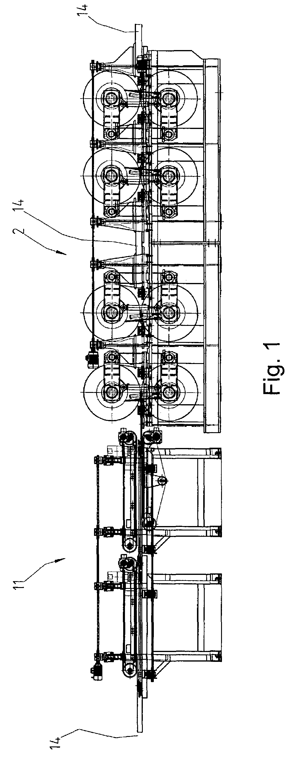
[0033]Turning now to the drawings, and referring first to the FIG. 1, the machine for front joining and sticking of oblong wood workpieces by toothed front joints is constructed of the entrance conveying line 1 and flow press 2, which follow each other in a row and are interactively transitionally joined in the way that oblong workpieces 14 travel through them fluently and in a given sequence, as a rule in the direction of their longitudinal axes.

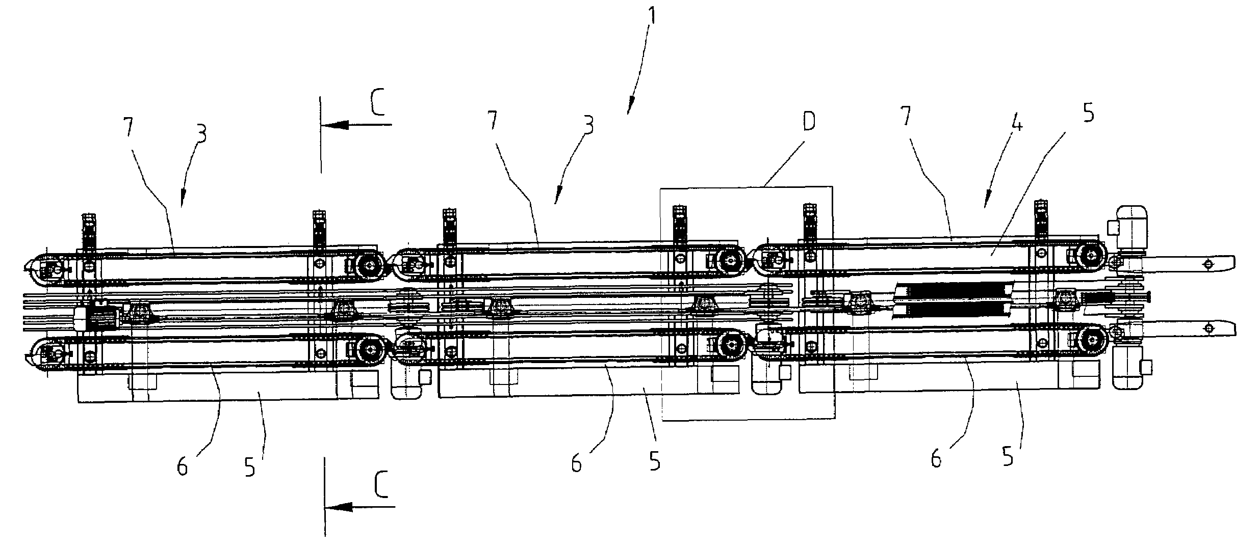
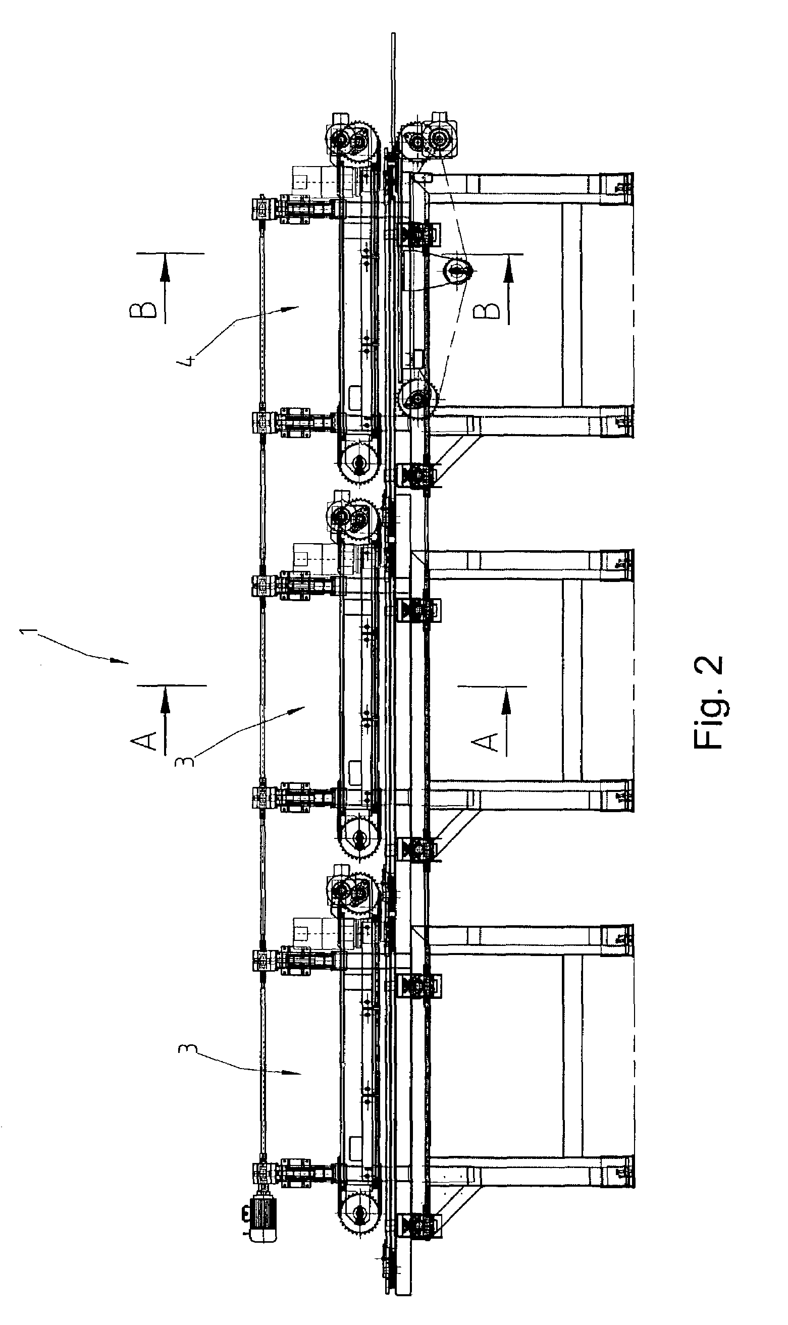
[0034]The conveying line 1 is constructed of at least one or more entrance conveyors 3, and as a rule of one but likewise possible of more exit conveyors 4, which follow each other in a row along the same central axis, and as a rule they touch each other. Each entrance conveyor 3 and exit conveyor 4 form side chain units 6 and 7 with the drive 11 and drive 12, and the pressing conveyor 9 with the drive 13, and they are all together placed on the housing 5. Side chain units 6 and 7 of the same type that follow each other in a row, and side c...


PUM

PropertyMeasurementUnit
Thicknessaaaaaaaaaa
Forceaaaaaaaaaa
Pressureaaaaaaaaaa

Abstract

Machine for front joining and sticking of oblong wood workpieces by toothed front joints and referential procedure consists of the flow press and entrance conveying line, and solves the problem of simple and quality front joining and sticking of workpieces, which travel through them fast and fluently in a consecutive row, irrespective of possible yet allowed curvature and dimensional deviation. This is enabled by the construction of entrance conveyors and exit conveyors of the conveying line, equipped with mechanisms for adjustment of side chain units, and with elastic couplings, whereby inside the side chain units the elastic insertions are placed, and inside pressing conveyors other elastic insertions are placed. Joints among individual entrance conveyors, among individual exit conveyors, and among conveyors are likewise elastic constructions by means of adjustable screws placed between fixed cantilevers, and between tension cantilevers. It is further enabled by the construction of entrance units and exit units in the flow press, or by the construction of pushing wheel pairs inside them, and which are simultaneously driven by the central driving coupling. For this purpose, each wheel pair is equipped with a pair of flexible cranks, the cylinder for pressure adjustment, the cylinder for position adjustment, the mechanism for interactive distance adjustment. Pushing wheel pairs also have the cylinder for the horizontal shift regulation and the shift-meter with which the force meter is connected, and which is placed at the end of the last pushing wheel pair.

Description

FIELD OF THE INVENTION[0001]The subject of the invention is a machine for front joining and sticking of oblong wood workpieces by toothed front joints and referential procedure, or more precisely, it is a machine for pressing and sticking of front toothed surfaces, which consists of a flow press with elastically constructed rotary elements, and before a flow press there is placed a conveying line, which consists of several functionally connected conveying surfaces for conveying workpieces, and the position of the individual transmission coupling can in both be adjusted.BACKGROUND OF THE INVENTION[0002]According to the international patent classification this submitted invention likely belongs to B 30B 3 / 04, B 30B 5 / 02, B 65G 15 / 14, B 65G 17 / 48 and B 30B 15 / 16.[0003]There are two basic solutions of the machine or of front joining and sticking of oblong wood workpieces mode respectively, preferentially for toothed front joints, known to us, and which have already for some time been ap...

Claims


Application Information

Patent Timeline
IPC IPC(8): B23D59/00B27B1/00B65G15/20B30B3/00B27M3/00B30B5/00B30B15/00B65G15/00B65G17/00
CPCB27M3/002
Inventor LEDINEK, GREGORLEDINEK, PAVEL
Owner LEDINEK GREGOR
Learn More