Radiation concentrator incorporating compound confocal uneven parabolic primary reflector, tailored secondary reflector and tailored receiver

a technology of compound confocal and uneven parabolic, which is applied in the field of radiation concentrators, can solve the problems of inability to achieve the high concentrations that non-imaging concentrators can deliver, the cpc will have to be impractically tall, and the optics, etc., and achieves the effect of convenient implementation

Inactive Publication Date: 2018-03-08
NOBLE NEVIN
View PDF2 Cites 4 Cited by
  • Summary
  • Abstract
  • Description
  • Claims
  • Application Information

AI Technical Summary

Benefits of technology

[0013]It is also possible to construct a primary-secondary combination of first concentrator where the rim angles of the primary parabolic reflectors are near 90°. In such a construction, the receiver will be very close to the

Problems solved by technology

But for concentrating radiation from very far away sources like the sun, the CPC will have to be impractically tall; and hence cannot be use as an ideal solar collector.
Imaging concentrators, such as parabolic reflectors are much more compact but they cannot achieve high concentrations that non-imaging concentrators can deliver.
A parabolic reflector of rim angle approximately 9° has its focus at a very large distance which makes it an impractical design.
A parabolic reflector of rim angle approximately 45° and 40° will have its focus, and thereby the receiver, away from the aperture; which makes the design difficult to track the sun.
Reflectors which are made of glass will not be able to withstand the thermal shock and breaks.
This makes

Method used


Image

  • Radiation concentrator incorporating compound confocal uneven parabolic primary reflector, tailored secondary reflector and tailored receiver
  • Radiation concentrator incorporating compound confocal uneven parabolic primary reflector, tailored secondary reflector and tailored receiver
  • Radiation concentrator incorporating compound confocal uneven parabolic primary reflector, tailored secondary reflector and tailored receiver

Examples


Embodiment Construction

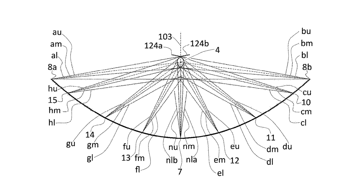
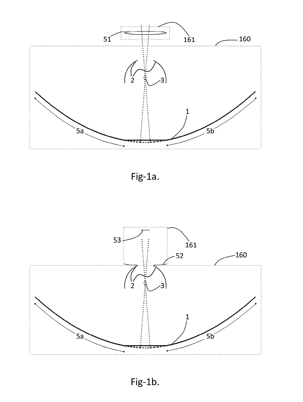
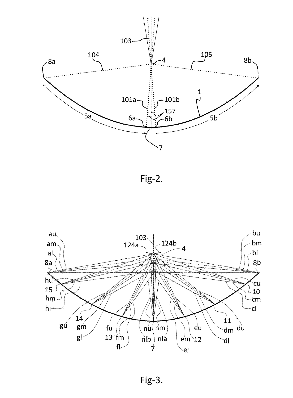
[0033]To clearly illustrate the features, geometry and principles of the invention the cross sectional view of various exemplary embodiments of the invention and the trajectory of light through them are described in the following part. The various embodiments described are trough type radiation concentrators, suitable for different distant radiation sources which subtends different angles at the aperture of the concentrator.

[0034]Please refer to FIG. 1a; this embodiment of the invention, a trough type radiation concentrator, includes the main concentrator (160) consisting of a primary reflector (1), a two part secondary reflector (2), a common receiver (3) and a lens (51) as the auxiliary concentrator (161). Please refer to FIG. 1b; this embodiment of the invention, a trough type radiation concentrator, includes the main concentrator (160) consisting of a primary reflector (1), a two part secondary reflector (2), a common receiver (3) and a combination of reflectors (52 and 53) as t...


PUM


Abstract

A radiation concentrator incorporating a main radiation concentrator (160) and an auxiliary radiation concentrator (161) that concentrates the incident radiation to the common receiver (3) is presented. The primary reflector (1) of the main concentrator (160) consists of two confocal parabolic reflectors (5a &5b) on either side of the axial plane in such a way that their parabolic axes points at the centers of the diagonally opposite halves of the radiation source. The main concentrator (160) is configured in such a way that a part of the radiation reflected from every point on its primary reflector (1) is absorbed by the receiver (3) directly and its secondary reflector (2) reflects the other part of the radiation to the receiver (3). The auxiliary concentrator (161) concentrates a substantial part of the incident radiation, which would have been blocked by the secondary reflector (2), to the receiver (3).

Description

FIELD OF INVENTION[0001]This invention relates to radiation concentrators that employ parabolic reflectors which may be used as solar collectors, to collect solar energy in the form of thermal energy which in turn may be converted to electric energy as its receiver attains high temperature. The radiation concentrators may be a dish type (3D) concentrator or a trough type (2D) concentrator.PRIOR ART[0002]The efficiency of a solar collector depends upon the concentration achieved by it. The efficiency increases, as the concentration achieved increases. The ideal concentration (theoretically achievable maximum) for a 3-D concentrator is 1 / sin2θ and for a 2-D concentrator it is 1 / sin θ; where θ is half the angle subtended by the radiation source (2θ).[0003]The solar collectors according to the prior art include imaging concentrators like parabolic reflectors and non-imaging concentrators like compound parabolic concentrators (CPC), compound elliptical concentrators (CEC) etc. The non-im...

Claims


Application Information

Patent Timeline
IPC IPC(8): G02B19/00
CPCG02B19/0023G02B19/0042G02B19/0028G02B17/0808
Inventor NOBLE, NEVIN
Owner NOBLE NEVIN
Why Eureka
Try Eureka