Laser beam scanner

a laser beam and scanner technology, applied in the field of laser beam scanners, can solve the problems of wasting time, requiring two galvo-mirrors and a focusing component, and limiting the speed at which a laser based powder bed additive manufacturing process can proceed,

Pending Publication Date: 2021-07-29
RENISHAW PLC
View PDF0 Cites 3 Cited by
  • Summary
  • Abstract
  • Description
  • Claims
  • Application Information

AI Technical Summary

Benefits of technology

[0021]The termination optic and output ends of the optical fibres may be arranged in a pattern such that the same pattern of laser beam spots can be achieved on the working surface for a plurality of different scanning directions. The output ends of the optical fibres may be arranged in a rotationally symmetric pattern about an opt

Problems solved by technology

A rate at which a laser based powder bed additive manufacturing process can proceed is limited by the difficulty of getting the laser power to the powder bed in an agile and accurate way.
A disadvantage of multi-laser systems of this type is that each laser will require two galvo-mirrors and a focu

Method used


Image

  • Laser beam scanner
  • Laser beam scanner
  • Laser beam scanner

Examples


Embodiment Construction

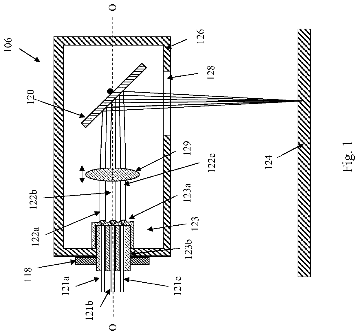
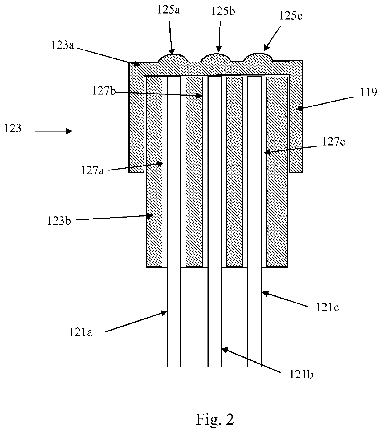
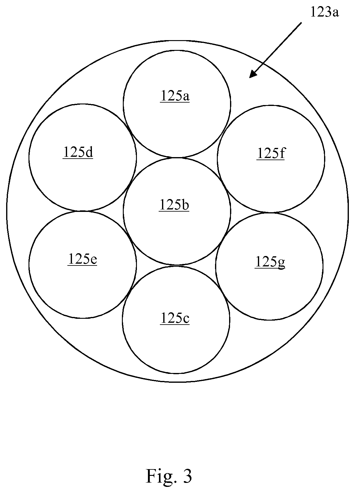
[0047]Referring to FIGS. 1 to 3, a laser beam scanner 106 according to an embodiment of the invention comprises a laser beams positioning optic 120, a plurality of optical fibres (in this embodiment seven optical fibres but only three 121a, 121b, 121c are shown) for delivering a plurality of laser beams 122a, 122b, 122c and a unitary fibre termination optic 123a aligned to direct the laser beams 122a, 122b, 122c from output ends of the optical fibres 121a, 121b, 121c to the laser beams positioning optic 120. The laser beams positioning optic 120 is movable relative to the fibre termination optic 123a to scan the laser beams 122a, 122b, 122c across a working surface 124.

[0048]In this embodiment, the laser beams positioning optic 120 comprises a pair of tiltable mirrors (only one of which is shown) mounted to rotate about orthogonal axis such that movement of the mirrors scans the laser beams 122a, 122b, 122c across the working surface 124 in two-dimensions. The tiltable mirrors are d...


PUM

PropertyMeasurementUnit
Fractionaaaaaaaaaa
Optical propertiesaaaaaaaaaa

Abstract

A laser beam scanner including a laser beams positioning optic, a plurality of optical fibres for delivering a plurality of laser beams and a fibre termination optic aligned to direct the laser beams from output ends of the plurality of optical fibres to the laser beams positioning optic. The laser beams positioning optic is movable relative to the fibre termination optic to scan the laser beams across a working surface.

Description

FIELD OF INVENTION[0001]This invention concerns a laser beam scanner and, in particular, but not exclusively, a laser beam scanner for an additive manufacturing (AM) apparatus, such as a powder bed additive manufacturing apparatus. The invention also concerns optics for the laser beam scanner, including a multi-laser beam optics, and methods of manufacturing the same.BACKGROUND[0002]In powder bed additive manufacturing objects are produced through layer-by-layer solidification of powder material. There are various methods of powder bed additive manufacturing, including selective laser melting (SLM) and selective laser sintering (SLS).[0003]In selective laser melting, a powder layer, such as a metal powder layer, is deposited on a powder bed in a build chamber and a scanner scans a laser beam across portions of the powder layer that correspond to a cross-section (slice) of the object being constructed. The laser beam melts the powder to form a solidified layer. After selective solidi...

Claims


Application Information

Patent Timeline
IPC IPC(8): B23K26/082B29C64/135B23K26/042
CPCB23K26/082B33Y30/00B23K26/042B29C64/135B23K26/0608B23K26/0643B23K26/0648B23K26/342Y02P10/25B22F10/366B22F12/45B22F12/49B22F10/28B22F12/44
Inventor WESTON, NICHOLAS JOHNMCFARLAND, GEOFFREY
Owner RENISHAW PLC
Why Eureka
Try Eureka