
Pet waste and refuse collection system and method

a technology for pet waste and refuse collection, applied in the field of new vacuum actuated system and method, can solve the problems of user repeatedly stabging the refuse, difficult use and/or immediate cleaning of the device, and constant plague of pet owners with having to collect and dispose of their pet waste, etc., and achieves the effect of allowing pet waste collection, convenient use, and low cost of purchase and operation

Inactive Publication Date: 2007-06-05
MOREIRA JOAO EMILIO DIAS
View PDF5 Cites 24 Cited by
  • Summary
  • Abstract
  • Description
  • Claims
  • Application Information

AI Technical Summary

Benefits of technology

[0008]An advantage of the present invention is that it permits collection of pet waste and / or refuse without requiring a user to bend or kneel. Thereby, providing assistance to the elderly and disabled who may not be as mobile.
[0009]Another advantage of the present invention is that permits the collection of pet waste and / or refuse without direct contact by the user. This is particularly relevant when collecting pet waste or other potentially toxic waste.
[0010]Still yet another advantage of the present invention is that it is easy to use and inexpensive to purchase and operate.
[0011]Yet still another advantage of an example embodiment of the present invention is that it permits vacuuming of pet waste and / or refuse without the need of an electric motor. The absence of an electric motor and power supply greatly reduces the weight of the present invention making it more user friendly.
[0012]The above summary of the invention is not intended to describe each illustrated embodiment or every implementation of the invention. The figures in the detailed description that follow more particularly exemplify these embodiments.

Problems solved by technology

Pet owners have continuously been plagued by having to collect and dispose of their pet's waste.
All of these devices are difficult to use and / or require immediate cleaning.
Although this device is adequate for its intended purpose it has a disadvantage of requiring the user to repeatedly stab the refuse to secure it to the handle.
The need to repeatedly stab the refuse expends time and energy of the user.

Method used


Image

  • Pet waste and refuse collection system and method
  • Pet waste and refuse collection system and method
  • Pet waste and refuse collection system and method

Examples


Embodiment Construction

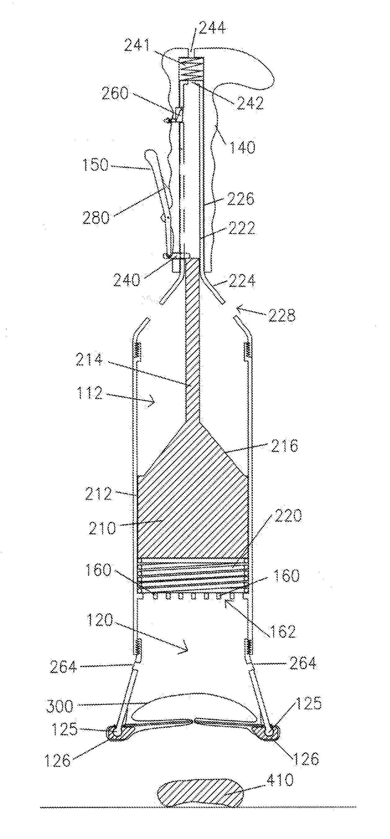
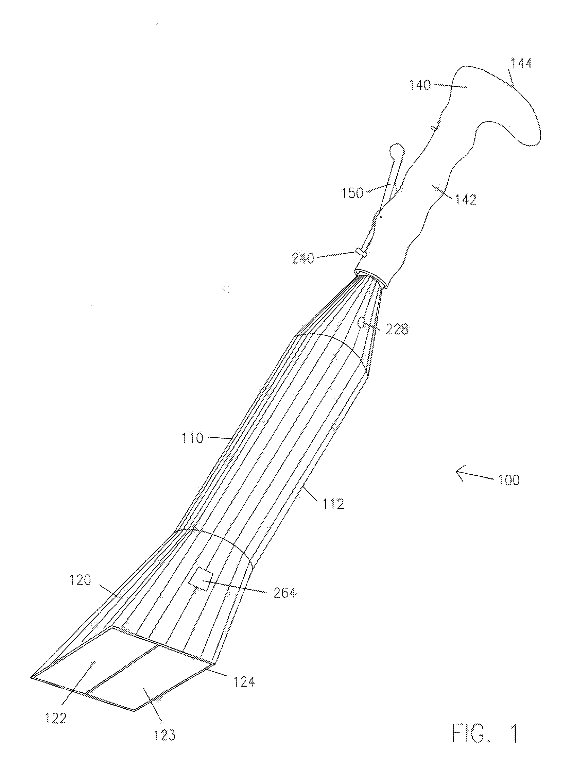
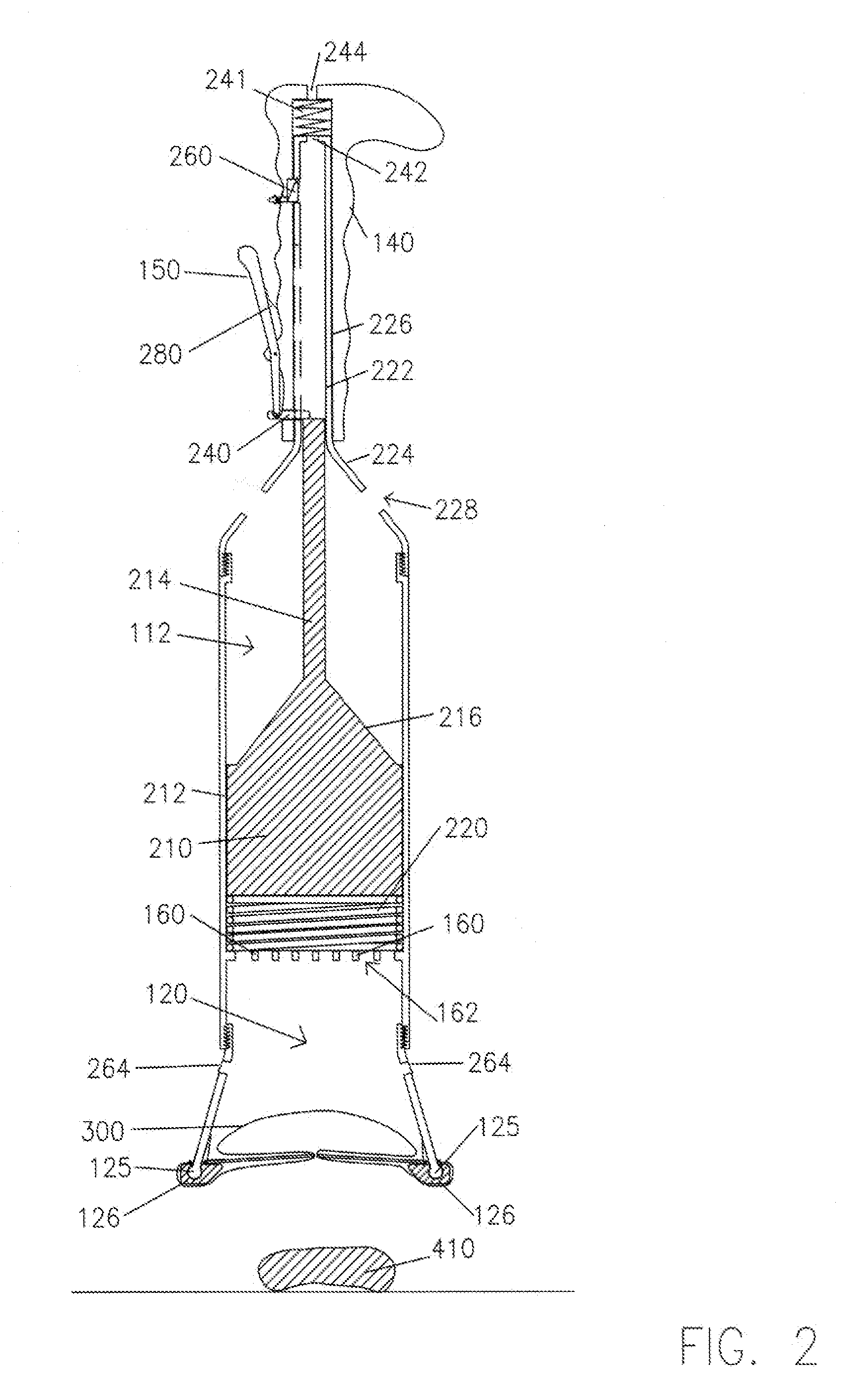
[0025]Referring to FIGS. 1–11, a pet waste and refuse collection system is indicated by the number 100. In an example embodiment of the present invention, the system 100 includes a housing assembly 110 and a vacuum assembly 200 operatively disposed in the housing assembly 110 to generate a vacuum to lift or collect pet waste, refuse and other debris into a portion of the housing assembly 110 from a subjacent ground or floor surface.

[0026]Referring to FIG. 1, the housing assembly 110 includes a vacuum chamber 112 for holding vacuum assembly 200. A waste-receiving chamber 120 is operatively disposed on or formed in an end of the vacuum chamber 112. The waste-receiving chamber 120 is in fluid communication with the vacuum chamber 112 such that when the vacuum assembly 200 is activated it creates a vacuum or suction in the waste-receiving chamber 120. In one example embodiment, the vacuum chamber 112 has a generally circular cross section. However, it may have any geometric cross sectio...


PUM


Abstract

System and method for vacuum actuated collection of pet waste and refuse. The system comprises a vacuum assembly operatively disposed in a vacuum chamber. The vacuum chamber is in operative fluid communication with a receiving chamber that receives and at least temporarily holds the vacuum lifted per waste and / or refuse. A handle assembly and actuator are operatively coupled to the vacuum assembly to control the generation of the vacuum. A collector may be disposed at least partially in the receiving chamber to permit easy disposal of the pet waste and refuse.

Description

BACKGROUND OF THE INVENTION[0001]1. Field of the Invention[0002]The present invention relates to pet waste and refuse collection and more particularly pertains to a new vacuum actuated system and method for collecting pet waste collection and other refuse.[0003]2. Description of the Prior Art[0004]Pet owners have continuously been plagued by having to collect and dispose of their pet's waste. Conventional devices and methods of collecting pet waste and other refuse have included shovels, scoopers, and bags. All of these devices are difficult to use and / or require immediate cleaning.[0005]Refuse collectors have traditional utilized an elongate handle having a nail or other sharpened device on its end. The nail is used to stab the refuse and transport it to a receptacle such as a bag. Although this device is adequate for its intended purpose it has a disadvantage of requiring the user to repeatedly stab the refuse to secure it to the handle. Only after it is secured to the handle can ...

Claims


Application Information

Patent Timeline
Patent Type & Authority Patents(United States)
IPC IPC(8): A01K29/00E01H1/12
CPCE01H1/1206E01H2001/1293
Inventor MOREIRA, JOAO EMILIO DIAS
Owner MOREIRA JOAO EMILIO DIAS
Learn More