Divergent beam two dimensional diffraction

Active Publication Date: 2020-01-30
BRUKER AXS
View PDF1 Cites 0 Cited by
  • Summary
  • Abstract
  • Description
  • Claims
  • Application Information

AI Technical Summary

Benefits of technology

The present invention is about an improved X-ray diffractometer that can collect two-dimensional X-ray data from a sample. It uses a divergent X-ray beam that illuminates a two-dimensional area of a surface of the sample. The detected X-ray signal is used to form a multi-dimensional dataset that indicates X-ray intensities in the one-dimensional detection area for each of the relative angular positions of the X-ray source, detector, and sample. This dataset can be used to analyze the morphological effects of crystallites in the sample, which can affect the quality of the X-ray diffraction data. The quality of the X-ray diffraction data can also be used to indicate the quality of qualitative and quantitative analyses performed on the sample. Additionally, the positioning mechanism can be reconfigured to collect information on the sample position, which can assist in performing subsequent analysis.

Problems solved by technology

However, in practice this is often not the case.
These deviations result in incorrect identification and quantification of the phases that are present.
In this method, the collected image is warped due to non-linear sampling of the reciprocal lattice.
In addition, generation of the necessary parallel spot is complex and expensive, relative to a simple line slit geometry, and produces a less intense signal.
Moreover, the relatively small area of the specimen 116 being examined can bias the result by accentuating localized grain size and preferred orientation effects as well as being susceptible to non-homogeneous distributed phases.
However, the need for a parallel beam with narrow aspect ratio or heavily asymmetric measurement geometry results in a weaker signal and reduced sample coverage relative to the simple linear slit geometry.
However, both methods require specialized beam conditioning to ensure sufficient resolution, the former requiring the beam to be a small parallel spot while the latter requires the beam to be either a narrow parallel line or a broad parallel line with data collected in a positive asymmetric measurement geometry.
This results in a relatively high overall tool cost, an increase in beam path complexity, a reduction in integrated flux on the sample surface and a reduction in specimen sampling.

Method used


Image

  • Divergent beam two dimensional diffraction
  • Divergent beam two dimensional diffraction
  • Divergent beam two dimensional diffraction

Examples


Embodiment Construction

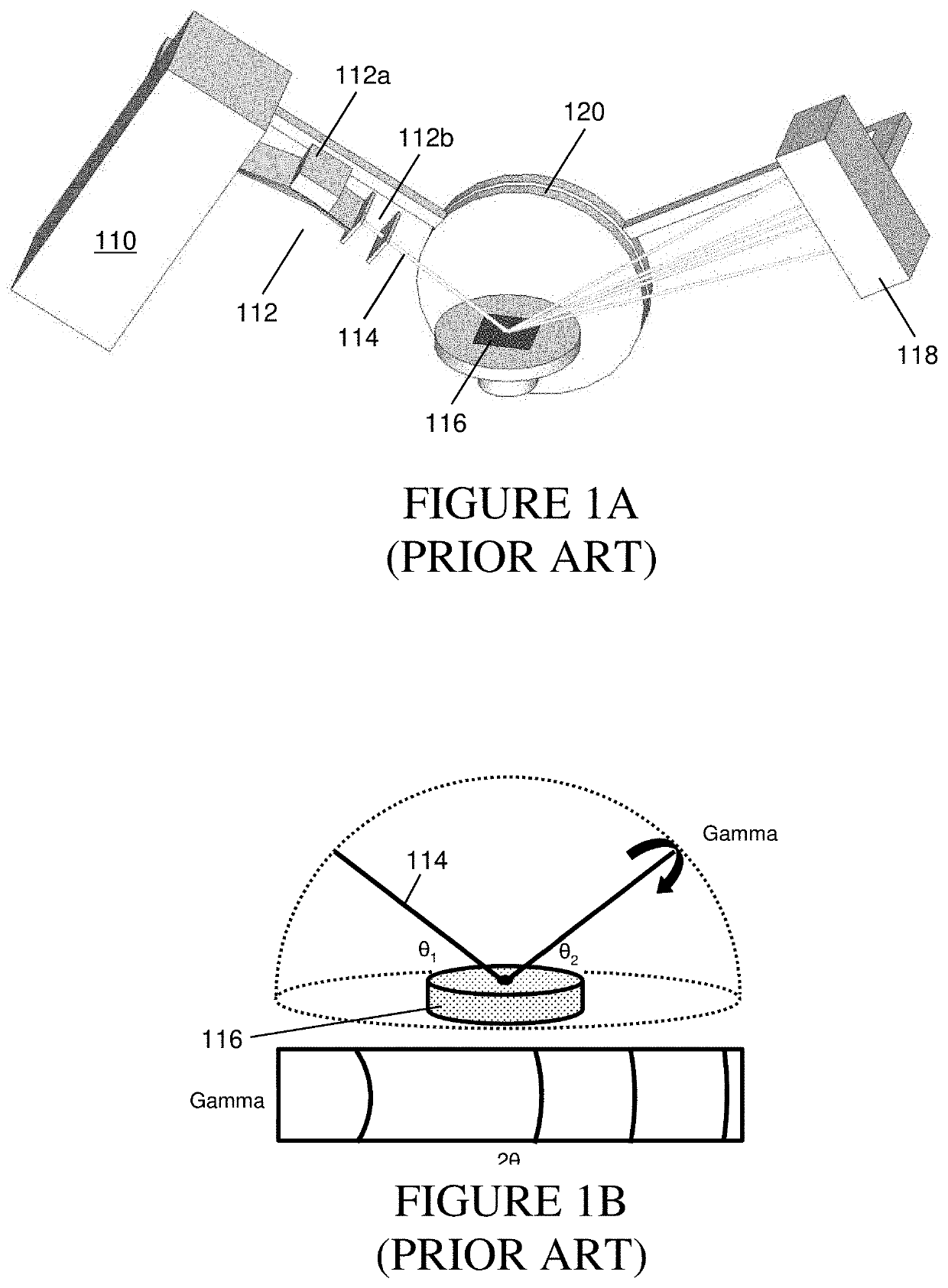
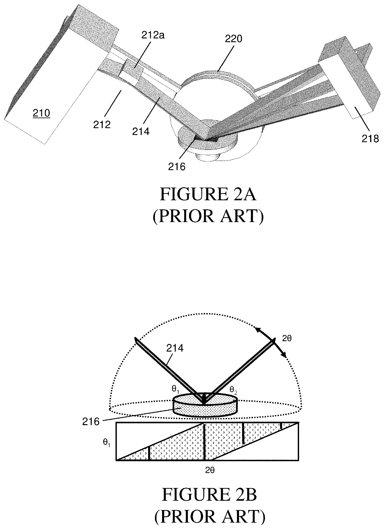
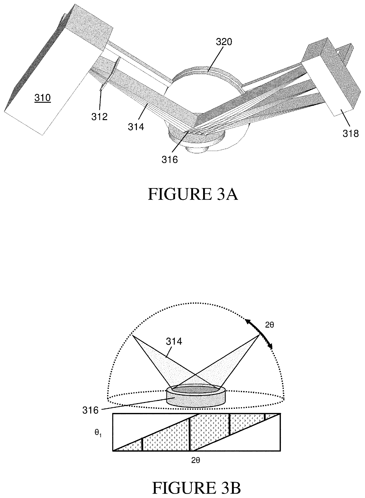
[0025]FIG. 3A is a schematic representation of a two-dimensional X-ray diffraction method that uses an X-ray beam source 310 that produces a divergent X-ray source beam 314 that is incident on a sample material 316. The beam from source 310 first passes though an aperture 312 that limits the size of the beam. The aperture 312 may be of different configurations and, in an exemplary embodiment, uses one or more metallic surfaces that form a slit in a direction perpendicular to the beam direction so as to limit the size of the beam in the direction of divergence. The aperture 312 is precisely positioned relative to the source 310, and is moved with the source when the source is repositioned. This replaces the conditioning optics used in prior art systems, such as the optics 212 used with the parallel beam method of FIG. 2A, which typically include a very expensive X-ray mirror 212a, or the optics 112 of the side tilt method of FIG. 1A, which require a similar mirror 112a as well as a s...


PUM


Abstract

A two-dimensional X-ray diffractometer uses an X-ray source that emits a divergent beam toward a sample under test. The divergent beam has a substantially fixed width in a first direction perpendicular to its propagation direction, and a thickness in a second direction perpendicular to the propagation direction that increases proportionally to a distance from the source. An aperture may be used to block a portion of the beam in the second direction, and the sample is positioned so that the beam illuminates a two-dimensional area of the sample surface. The detector detects an X-ray signal diffracted from the sample across a two-dimensional detection area, and may use a one-dimensional detector array that collects diffracted X-ray signal at a number of different positions. The source, detector and sample may be mounted to a goniometer to maintain them in a desired relative orientation.

Description

BACKGROUND OF THE INVENTIONField of the Invention[0001]This invention relates generally to the field of X-ray diffraction analysis and, more specifically, to an improved method of X-ray diffraction analysis of powder samples.Description of the Related Art[0002]Two-dimensional x-ray diffraction refers to x-ray diffraction applications with a two-dimensional diffraction image and corresponding data reduction and analysis. A two-dimensional diffraction pattern contains far more information than a one-dimensional profile collected with a conventional diffractometer. In recent years, usage of two-dimensional (2D) detectors has dramatically increased due to advances in detector technology, point beam x-ray optics, and computing power. A two-dimensional diffractometer is a diffraction system with the capability of acquiring a diffraction pattern in two-dimensional space and analyzing 2D diffraction data accordingly.[0003]A two-dimensional diffractometer system typically uses an X-ray gener...

Claims


Application Information

Patent Timeline
IPC IPC(8): G01N23/207G01N23/20016
CPCG01N23/20016G01N23/2076G01N23/20008G01N2223/056G01N2223/1016G01N23/207
Inventor GIENCKE, JONATHAN
Owner BRUKER AXS
Why Eureka
Try Eureka