Active assist orthotic

a technology of active assist and orthotics, applied in the field of orthotics, can solve the problems of joint stiffness, ineffectiveness, and pain in exercises, and achieve the effects of reducing the apparent weight of the orthotic, less apparent weight, and more evenly distributed device weigh

Active Publication Date: 2022-03-29
THE ARIZONA BOARD OF REGENTS ON BEHALF OF THE UNIV OF ARIZONA
View PDF17 Cites 0 Cited by
  • Summary
  • Abstract
  • Description
  • Claims
  • Application Information

AI Technical Summary

Benefits of technology

[0007]It is an objective of the present invention to provide a motor-hinged joint brace that simultaneously stabilizes a joint and provides frequent motion to prevent the buildup of scar tissue and maintain the range of motion of the joint, as specified in the independent claims. Embodiments of the invention are given in the dependent claims. Embodiments of the present invention can be freely combined with each other if they are not mutually exclusive.
[0008]In some aspects, a hinged joint orthotic for stabilizing a hinge joint of a user while providing assistance during active flexion and extension movement of the joint is disclosed. Non-limiting examples of the hinge joint of the user include an elbow, knee, wrist, ankle, etc. While performing flexion and extension movement in the arm, the orthotic can actively assist the patient in moving the limb, e.g. arm or leg, to a predetermined angle. Without wishing to limit the invention to a particular theory or mechanism, the assisted flexion and extension movement of the joint effectively prevents stiffness or decreases stiffness associated with trauma or an underlying condition, while decreasing the chances of further injury.
[0010]In some embodiments, the first alignment plate and the second alignment plate are configured to be attached to a brace having the limb disposed therein, and the hinge may be positioned adjacent to the joint and preferably co-axial to the joint. Without wishing to limit the invention to a particular theory or mechanism, the alignment of the stepper motor and the bevel gear on the first alignment plate positions the stepper motor away from the affected joint and closer to a center of the limb and to a center of the user's body, thus reducing an apparent weight of the orthotic experienced by the user. In some embodiments, the stepper motor can apply a torque to the bevel gear, which transfers said torque to a gear shaft of the bevel gear. Thus, rotation of the gear shaft drives rotation of the hinge, which moves the first alignment plate and the second alignment plate into a position reflecting the selected angle. The brace moves simultaneously with the movement of the plates, thereby positioning the limb at the selected angle.
[0013]According to other aspects, the present invention features an active assist elbow orthotic for stabilizing an elbow of a user while providing active assistance for flexion or extension movement of an arm of the user to prevent stiffness or decrease stiffness of the elbow. The elbow orthotic may comprise an elbow brace that stabilizes the elbow and an active assist mechanism that provides assistance to the user as the user exerts effort to move the arm to a selected elbow angle. In some embodiments, the elbow brace may comprise an upper component operatively coupled to a lower component via a first hinge. The elbow brace is configured to be worn on the arm such that an upper arm is disposed in the upper component, a forearm is disposed in the lower component, and the first hinge is adjacent to the elbow. The first hinge permits flexion or extension movement of the arm from the elbow, which can comprise a plurality of elbow angles, each elbow angle being a specified degree formed by the elbow.
[0014]In other embodiments, the active assist mechanism may comprise a first alignment plate operatively coupled to the upper component of the elbow brace, a second alignment plate operatively coupled to the lower component of the elbow brace and pivotably coupled to the first alignment plate via a second hinge co-axial with the first hinge and elbow, a bevel gear disposed on the first alignment plate at or near the hinge and operatively coupled to the hinge, and a stepper motor disposed on the first alignment plate and aligned with the bevel gear. The stepper motor can have a motor shaft operatively coupled to the bevel gear. Preferably, the alignment of the stepper motor and the bevel gear on the first alignment plate positions the stepper motor away from the affected elbow joint and closer to a center of the arm and to a center of the user's body, thus reducing an apparent weight of the orthotic experienced by the user. The stepper motor is configured to apply a torque to the bevel gear, which transfers said torque to a gear shaft of the bevel gear. Rotation of the shaft drives rotation of the second hinge, thereby moving the first alignment plate and the second alignment plate into a position reflecting a selected angle of the plurality of elbow angles. The elbow brace moves simultaneously with the movement of the plates, thus positioning the arm at the selected angle.
[0020]One of the unique and inventive technical features of the present invention is the alignment of the stepper motor and the bevel gear on the first alignment plate. As used herein, the bevel gear comprises two rotating gears oriented such that their rotational axes intersect at a 90° angle. As shown in FIG. 2, the first rotating gear is disposed on the first alignment plate at the hinge and co-axial with the gear shaft. The second rotating gear is also disposed on the first alignment plate and perpendicular to the first rotating gear. Thus, the second rotating gear is aligned with the stepper motor. Without wishing to limit the invention to any theory or mechanism, it is believed that this configuration advantageously allows for the stepper motor to be positioned closer to the center of body, e.g. on the upper arm and closer to the shoulder, which reduces the apparent weight of the orthotic experienced by the user. The resistance to rotational acceleration, also known as rotational inertia or angular mass, increases by the square of the distance of a mass from the center of rotation, thus by placing a mass closer to the center of rotation, this decreases the apparent weight that is felt by the user. In the present invention, the weight of the motor is near the center of rotation of the shoulder and of the upper arm. Moreover, the weight of the device is more evenly distributed along the upper arm, which further reduces the apparent weight of the device. Another advantage of this configuration is that it eliminates the need for gear belts and pulleys thereby further reducing the weight of orthotic. None of the presently known prior references or work has the unique inventive technical feature of the present invention.

Problems solved by technology

Joint stiffness, such as elbow stiffness for example, is a common problem that is caused by the accumulation of fibrous tissue in the joint and surrounding structures during the healing process.
It is made worse by the rigid bracing that is used to stabilize the elbow.
It is commonly treated with range of motion exercises performed daily, but the exercises can be painful and are often ineffective.

Method used


Image

  • Active assist orthotic
  • Active assist orthotic
  • Active assist orthotic

Examples


example

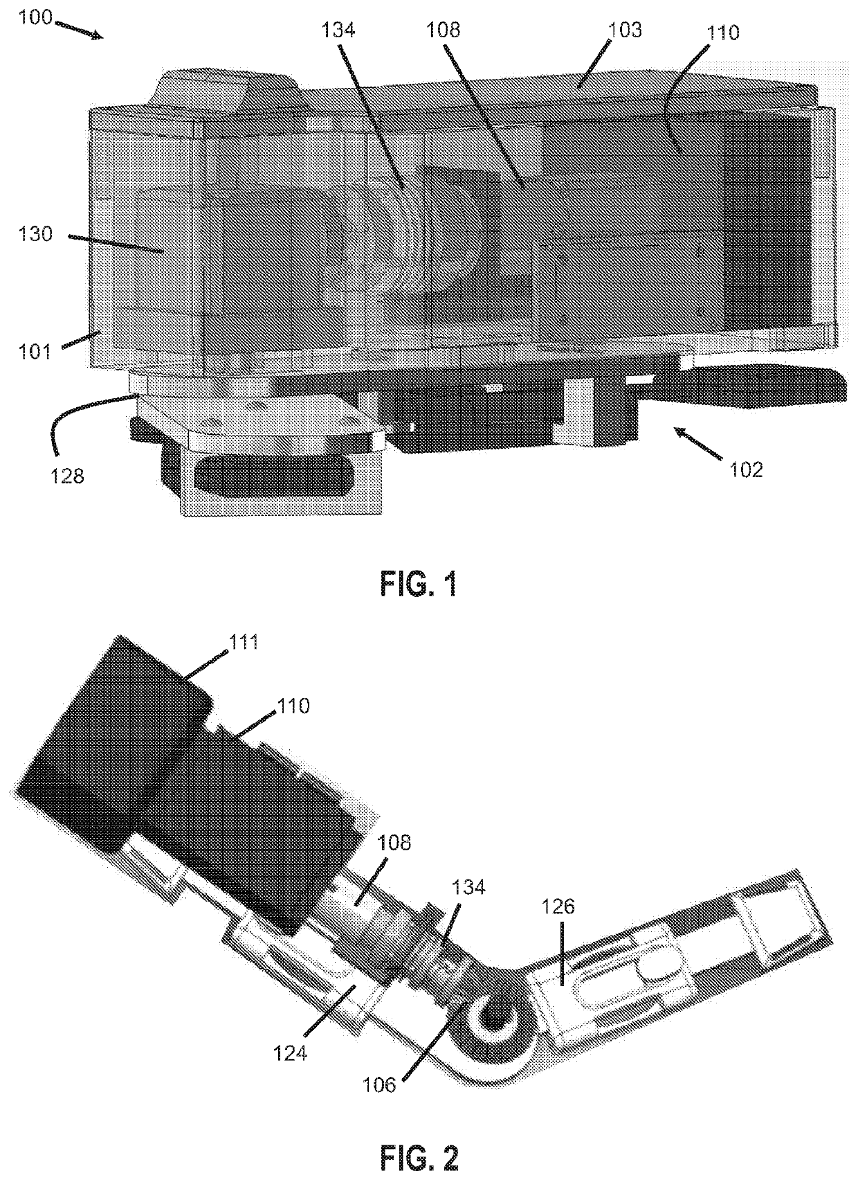
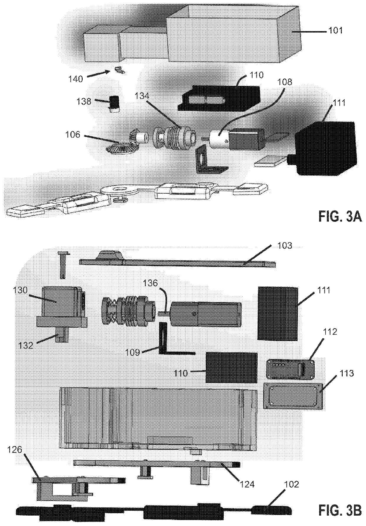
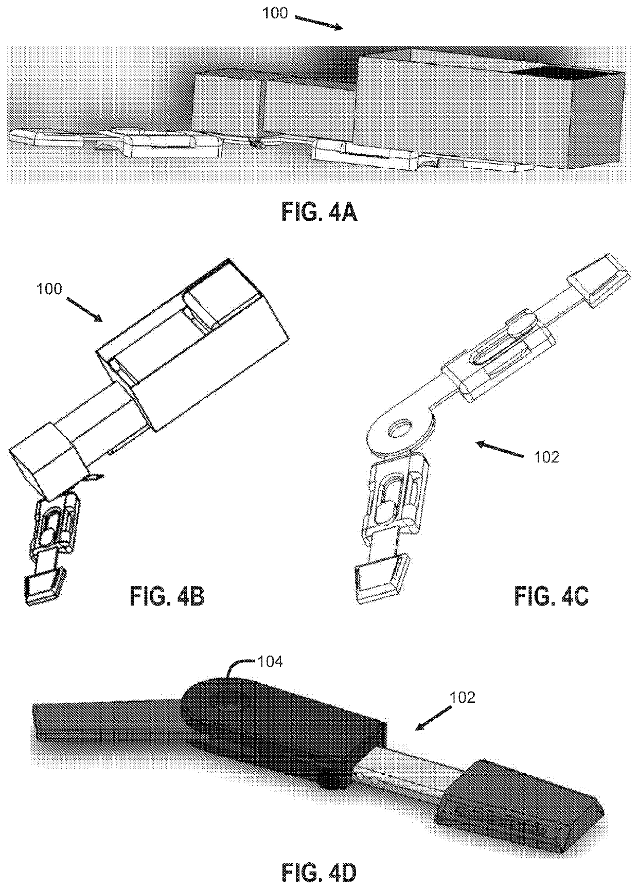
[0093]Without wishing to limit the present invention to any particular embodiment, the following is a description of example components comprising the active assist elbow orthotic of the present invention. Equivalents or substitutes are within the scope of the invention.

[0094]In preferred embodiments, the motor-hinged elbow orthotic can maintain as much range of motion in the joint throughout a healing process while also breaking down the scar tissue in the joint. The device can aid recovery after surgery and has the advantage over physical therapy of being wearable and user controllable. While performing the flexion / extension movement in the arm, the orthotic can actively assist the patient into moving the arm to a predetermined angle as prescribed by a physician.

[0095]In one embodiment, the active assist elbow orthotic system is broken up into two main distinctions: the arm brace including the mechanical and electrical components and the display interface (118), herein referred to...


PUM


Abstract

An elbow brace is retrofitted to provide a motor-hinged orthotic elbow brace that stabilizes the elbow of a user and provides assisted motion to prevent or reduce buildup of scar tissue and maintain the range of motion of the elbow. A user interface is coupled to the brace for tracking exercises and the angle of the elbow brace. The orthotic elbow brace can also assist the patient in moving the arm at one or more predetermined angles according to physician instructions.

Description

CROSS REFERENCE[0001]This application is a 371 and claims benefit of PCT / US18 / 30285 filed Apr. 30, 2018, which claims benefit of U.S. Provisional Application No. 62 / 492,760, filed May 1, 2017, the specification(s) of which is / are incorporated herein in their entirety by reference.FIELD OF THE INVENTION[0002]The present invention relates to an orthotic, more specifically, to a hinged brace having an active assistance mechanism that motorizes said hinge and provides active assistance to the wearer.BACKGROUND OF THE INVENTION[0003]Joint stiffness, such as elbow stiffness for example, is a common problem that is caused by the accumulation of fibrous tissue in the joint and surrounding structures during the healing process. It can occur after surgery or trauma (e.g. elbow dislocation), or can occur congenitally (e.g. arthrogryposis) or developmentally. It is made worse by the rigid bracing that is used to stabilize the elbow. It is commonly treated with range of motion exercises performe...

Claims


Application Information

Patent Timeline
Patent Type & Authority Patents(United States)
IPC IPC(8): A61F5/01
CPCA61F5/013A61F2005/0155A61F2005/0158A61F5/00
Inventor LATT, L. DANIELSVEIVEN, MICHAEL CAMERONKOZIOL, BLAKELEY LOUISEGRIJALVA, CARISSA LIANAHSIEH, JUSTINBARREDA, ADRIANASHIMON, TIMOTHY
Owner THE ARIZONA BOARD OF REGENTS ON BEHALF OF THE UNIV OF ARIZONA
Why Eureka
Try Eureka