Snap-in coupling comprising a spring clamp

a spring clamp and coupling technology, applied in the direction of couplings, threaded fasteners, screws, etc., can solve the problems of difficult to precisely set the absolute value of the mounting, the coupling cannot be released by acceptable forces, etc., and achieve the same vibration decoupling characteristics and optimal chemical and thermal deformation resistance

Active Publication Date: 2007-06-05
BOLLHOFF VERBINDUNGSTECHNIK GMBH
View PDF14 Cites 50 Cited by
  • Summary
  • Abstract
  • Description
  • Claims
  • Application Information

AI Technical Summary

Benefits of technology

[0011]A further advantage of the present invention is that the absolute values of the mounting and dismounting forces of the snap-in coupling may be very precisely controlled and set by spring clamp characteristics such as material thickness, type of material, geometry, etc. The forces for closing and opening a certain snap-in coupling, therefore, are substantially less responsive to variations of the characteristics of the used plastic material than in the prior art.
[0012]Since the female coupling member consists not only of the metallic spring clamp but additionally of a plastic support member, the support member may be designed such that the snap-in coupling of the present invention will show substantially the same vibration decoupling characteristics as the above mentioned conventional snap-in couplings. Therefore the snap-in coupling of the present invention combines the advantageous properties of a metallic spring clamp and the vibration decoupling characteristics of a plastic coupling member.
[0013]While the spring clamp could be connected to the support member of the female coupling member so as to be releasable, preferably they are fixedly connected to each other by having a base plate of the spring clamp embedded in plastic material of the support member by injection moulding.
[0014]Preferably the spring clamp has a plurality of circumferentially spaced spring arms which snappingly engage the head portion of the male coupling member to provide said snap-in connection. The ends of the spring arms each comprise a holding portion and an insertion portion which are angled with respect to each other in V-shaped relationship. The head portion of the male coupling member has an annular groove matingly shaped with respect to the ends of the spring arms. As a result the insertion portion and the holding portion of the spring arms of the spring clamp may be shaped differently such that a smaller force is required to close the snap-in connection than to open the snap-in connection.
[0015]Preferably the support member of the female coupling member is made of a thermoplastic elastomeric material of optimal chemical and thermal deformation resistance while the spring clamp, as mentioned above, may be made of spring steel.

Problems solved by technology

For example, when they are subject to extremely low temperatures down to −40° C. to be encountered in cold climatic zones they will become so hard that the snap-in coupling cannot be released by acceptable forces.
Apart from the fact that the mounting and releasing forces are dependent on temperature it is relatively difficult to precisely set the absolute values of the mounting and, respectively, releasing forces for normal environmental conditions because the characteristics of the used plastic material as well as the geometry of the plastic female coupling member cannot be readily controlled.

Method used


Image

  • Snap-in coupling comprising a spring clamp
  • Snap-in coupling comprising a spring clamp
  • Snap-in coupling comprising a spring clamp

Examples


Embodiment Construction

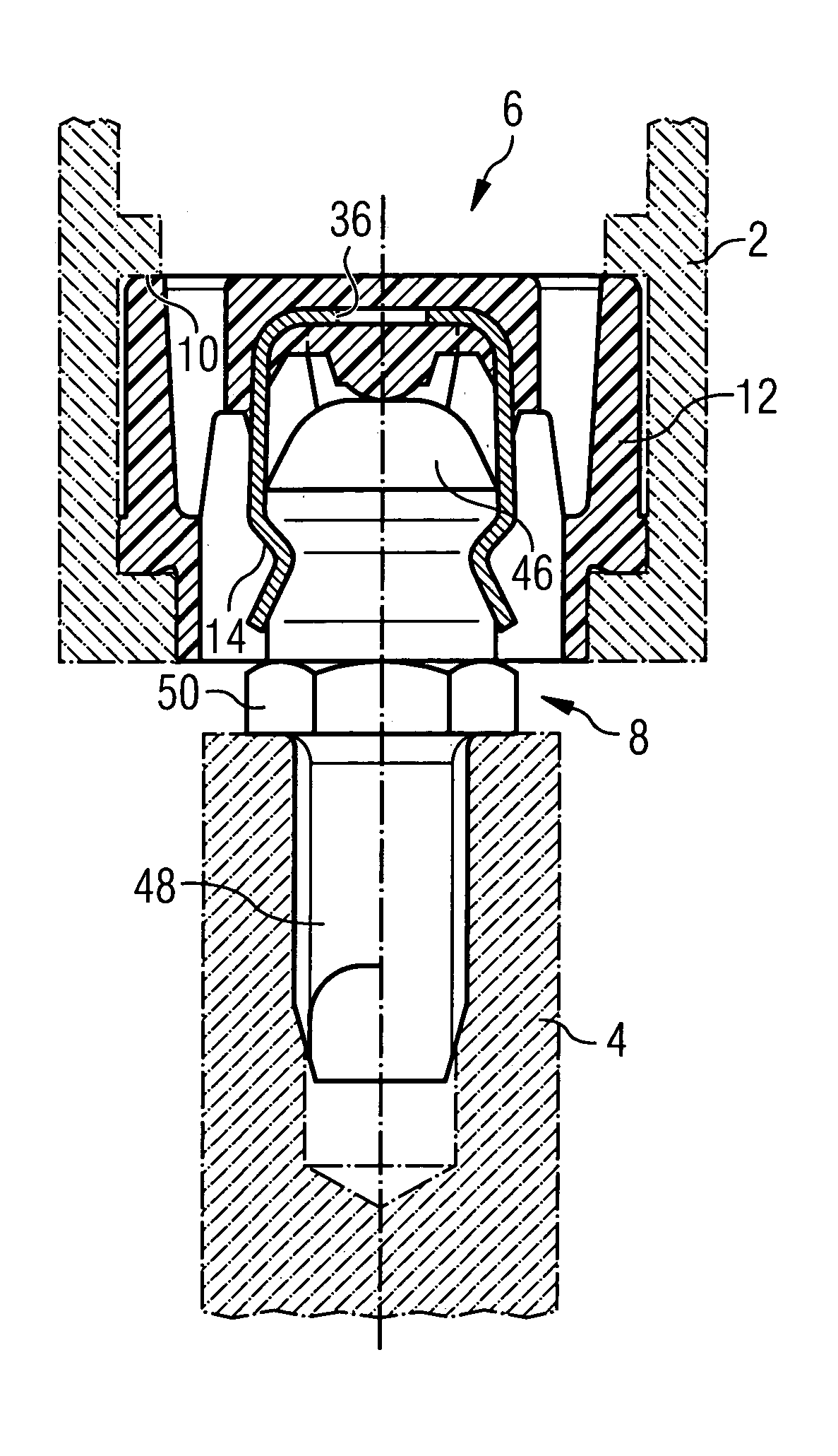
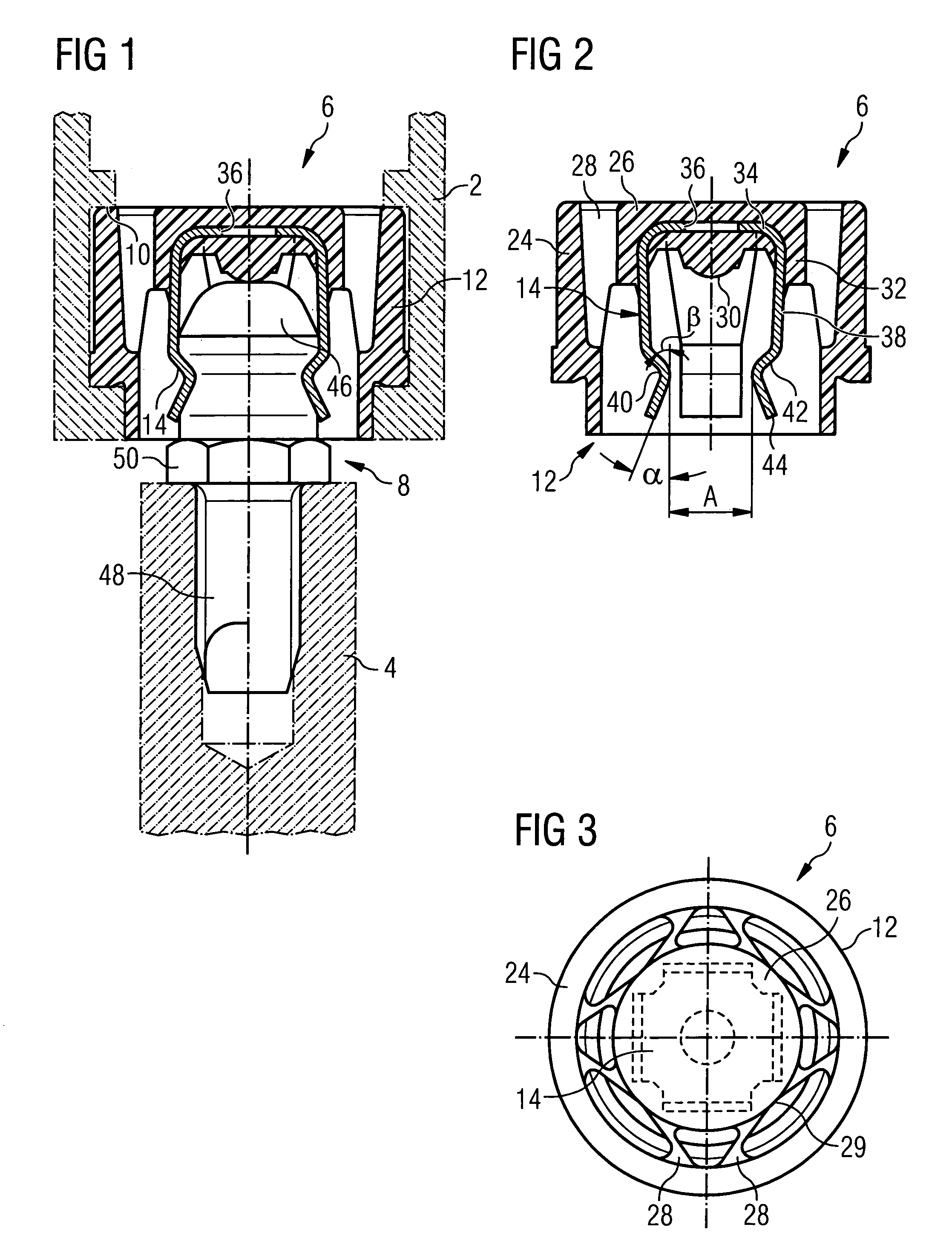
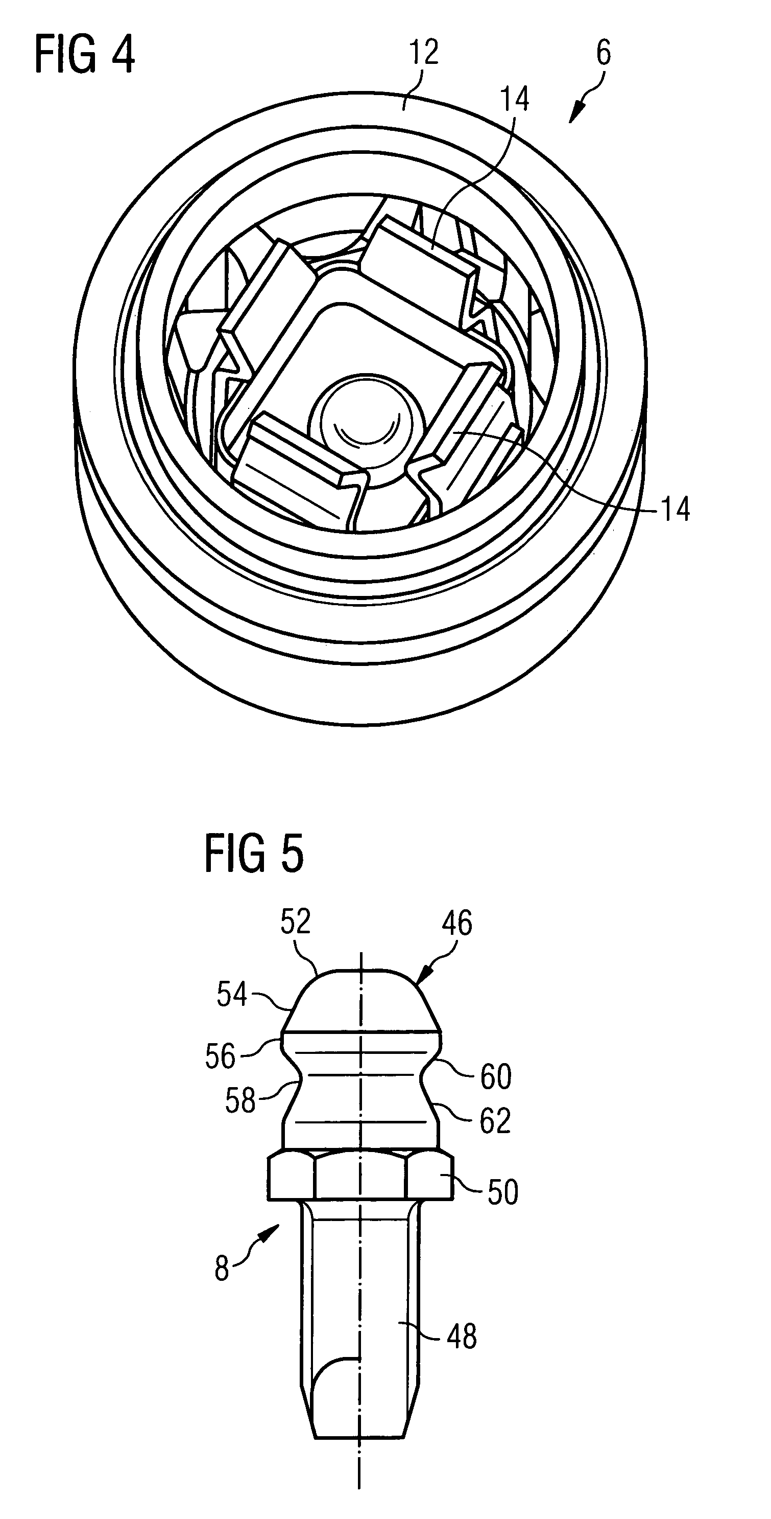
[0022]The snap-in coupling as shown in FIG. 1 is intended to releasably join a structural member 2 and a structural member 4 which may be for example structural members of an automotive vehicle to be releasably connected to each other. The snap-in coupling consists of a female coupling member 6 and a male coupling member 8; the female coupling member 6 may be inserted into a socket 10 of the structural member 2, and the male coupling member 8 may be fixed to the structural member 4.

[0023]In the embodiment as shown, the socket 10 is formed by a recess of the structural member 2 which is of part annular or horseshoe-shape so that the female coupling member 6 may be laterally inserted into the socket 10. In any case the socket 10 may be of a design as shown in the above-mentioned DE 198 36 108 A1 or DE-GM 202 16 836 the disclosure of which is incorporated herein by reference.

[0024]As shown in FIGS. 1 and 2, the female coupling member 6 comprises a support member 12 and a spring clamp 1...


PUM


Abstract

A snap-in coupling for releasably connecting a first structural member and a second structural member. The snap-in coupling comprises a female coupling member comprising a plastic support member and a metallic spring clamp, said support member being insertable into a socket provided at said first structural member such that the female coupling member is retained therein, and a male coupling member comprising a mounting portion for being fixed to said second structural member, and a head portion. Said spring clamp and said head portion are arranged to snappingly engage each other when said female coupling member and said male coupling member are inserted into each other.

Description

FIELD AND BACKGROUND OF THE INVENTION [0001]The present invention relates to a snap-in coupling for releasably connecting a first structural member and a second structural member.[0002]DE 198 36 108 A1 discloses a snap-in coupling comprising an elastically deformable female coupling member and a male coupling member. The female coupling member is adapted to be inserted into a socket provided at said first structural member so as to be positively retained therein. It comprises a spherical female portion, an annular intermediate wall integral therewith and serving as an insertion portion, and a tubular outer wall integral with said intermediate wall, which outer wall engages a peripheral wall of the socket when the female coupling portion is inserted into the socket. The male coupling member comprises a head portion and a mounting portion adapted to be fixed to the second structural member.[0003]In this prior snap-in coupling the intermediate wall of the female coupling member is of c...

Claims


Application Information

Patent Timeline
Patent Type & Authority Patents(United States)
IPC IPC(8): F16C11/00F16D1/12F16B21/18F16B35/04F16B35/06F16C11/06
CPCF16B21/186F16B35/042F16B35/06Y10T403/60Y10T403/32196Y10T24/45775Y10T403/32803Y10T403/32631Y10T403/32778
Inventor SUBENBACH, RAINERRINTELMANN, JOCHENDEMBOWSKY, HANS-JOACHIMJODELEIT, MARTIN
Owner BOLLHOFF VERBINDUNGSTECHNIK GMBH
Why Eureka
Try Eureka