Active shift transmission, transmission control unit and automobile

a technology of transmission control unit and active shift, which is applied in the direction of electric propulsion mounting, transportation and packaging, gearing, etc., can solve the problems of weight reduction and cost, and achieve the effect of ensuring economical disadvantages and increasing the efficiency of regenerative braking

Active Publication Date: 2007-06-05
HITACHI ASTEMO LTD
View PDF11 Cites 50 Cited by
  • Summary
  • Abstract
  • Description
  • Claims
  • Application Information

AI Technical Summary

Benefits of technology

[0008]The object of the present invention is to solve the aforementioned problem and to provide a less costly active transmission control system for automobile use, while making an extensive use of the hybrid function.
[0009]The present invention provides a gear train configuration that disconnects an engine from the transmission without using a clutch. To put it more specifically, part of the gears is shifted to the side of the engine shaft side through modification of the layout of a gear with dog clutch, whereby engine disconnection is enabled, without allowing the number of the dog clutches to exceed that of the intermediate position type active shaft transmission system.
[0010]The present invention allows the engine to be disconnected from the transmission without increasing the number of the dog clutch, thereby increasing increase the efficiency in regenerative braking and ensuring economical disadvantages.

Problems solved by technology

This method involves a problem in that, when a regenerative braking function as a hybrid function is used, the engine brake is applied at all times. It goes without saying that this problem can be solved by arranging a clutch, but this does not bring about a reduction in the weight and cost.

Method used


Image

  • Active shift transmission, transmission control unit and automobile
  • Active shift transmission, transmission control unit and automobile
  • Active shift transmission, transmission control unit and automobile

Examples


first embodiment

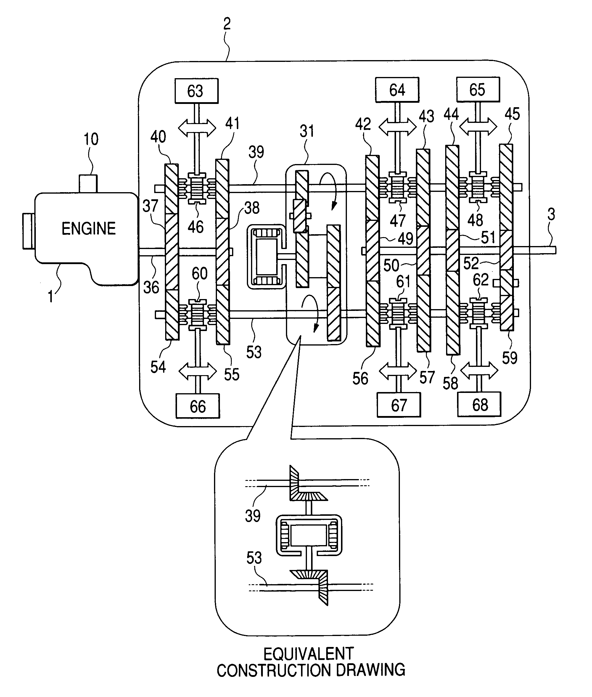
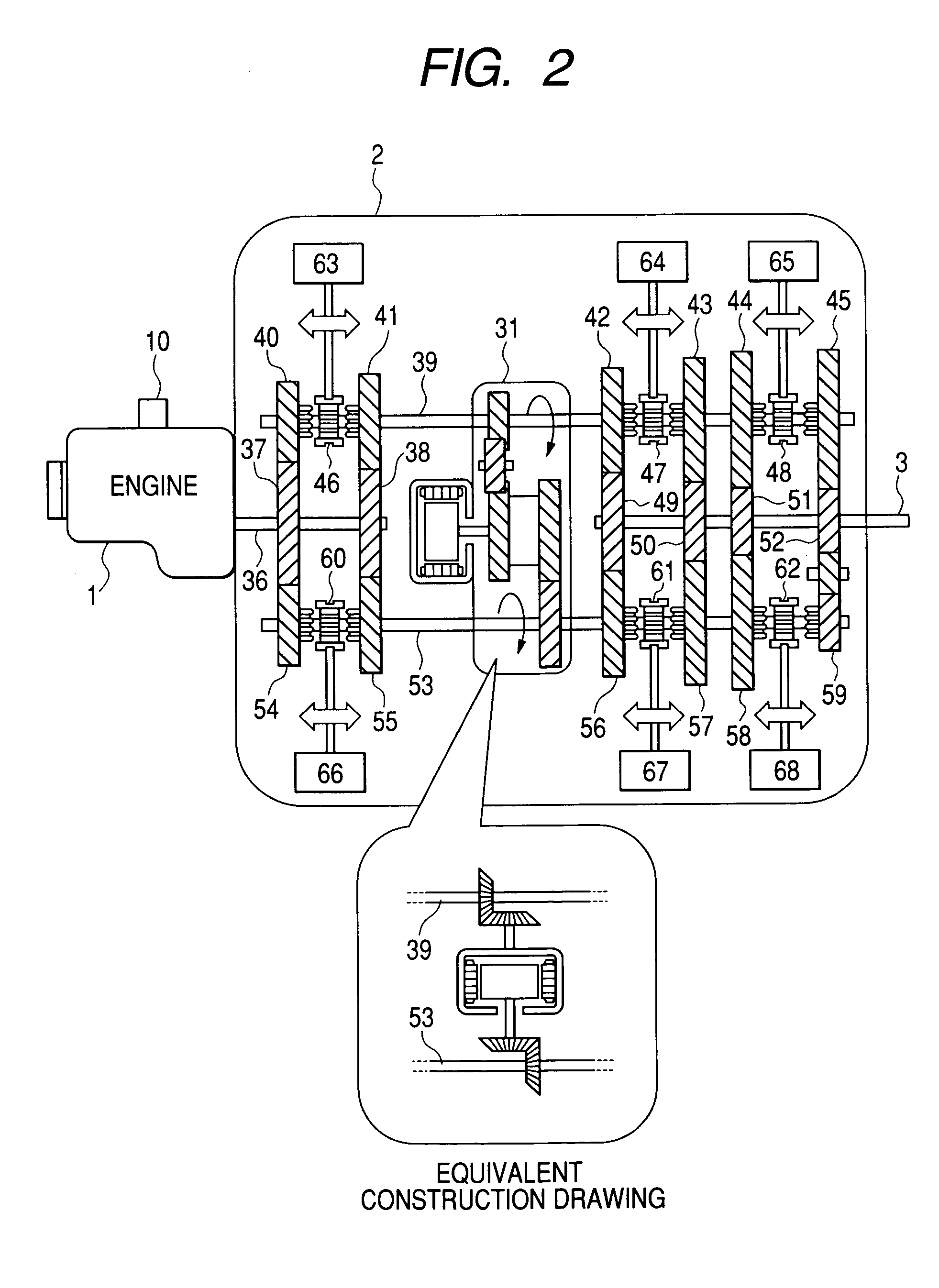
[0035]FIG. 2 is a block diagram of a transmission 2 representing the present invention. The output of the engine 1 is connected with a transmission input shaft 36. The transmission input shaft 36 is fixed with input gears 37 and 38. A first intermediate shaft 39 is arranged opposite to the input shaft 36, and transmission gears 40, 41, 42, 43, 44 and 45 are mounted rotatably on the first intermediate shaft 39. These transmission gears are equipped with dog clutches 46, 47 and 48 so that any one of the transmission gears can be engaged with the first intermediate shaft 39.

[0036]The transmission gears 40 and 41 of the first intermediate shaft 39 are meshed with the input gears 37 and 38, and the transmission gears 42, 43, 44 and 45 are meshed with driven gears 49, 50, 51 and 52.

[0037]A second intermediate shaft 53 is provided opposite to the input shaft 36, and the second intermediate shaft 53 is rotatably equipped with transmission gears 54, 55, 56, 57, 58 and 59. These transmission ...

second embodiment

[0078]FIG. 15 is a block diagram representing the transmission 2 as the present invention. What is different from FIG. 2 is that the transmission gear 40 of the first intermediate shaft 39 is used for backing up. Instead, gear ratio of the transmission gear 59 second intermediate shaft 53 is reduced to be used for sixth gear.

[0079]FIG. 16 shows an example of the operation mode of this transmission. In the present embodiment, the gear ratio is determined by a combination of two transmission gears. The engine torque is transferred from the input shaft 36 to either the first intermediate shaft 39 or second intermediate shaft 53, and is transferred from that intermediate shaft directly the output shaft 3. This mode is the drive mode, on the one hand. On the other hand, the assist mode is the mode where the engine torque is transferred to the output shaft 3 after having been transferred to another intermediate shaft through the motor. This is the same as the case in FIG. 3. The 1st, 2nd,...


PUM


Abstract

The object of the invention is to provide a less expensive active transmission control system for an automobile, capable of disconnecting an engine, without increasing the number of dog clutches.In an active shift transmission, a second intermediate shaft is provided between a transmission input shaft connected with an engine and a transmission output shaft, and the transmission ratio is determined by the product of gear ratios of two sets of transmission gears. Further, a differential gear box is connected between both intermediate shafts and a motor is connected to the third shaft of this differential gear box, so that the engine torque is borne by the motor on a temporary basis, whereby active transmission is performed. When the transmission gear of the input shaft is released, the engine rotation loss at the time of regenerative braking can be eliminated by disconnecting the engine.

Description

CLAIM OF PRIORITY[0001]The present application claims priority from Japanese application serial no. 2003-312078, filed on Sep. 4, 2003, the content of which is hereby incorporated by reference into this application.FIELD OF THE INVENTION[0002]The present invention relates to the control of a transmission, in particular, to the art of reducing a transmission shock by cooperating control of an engine, motor and transmission.BACKGROUND OF THE INVENTION[0003]In the prior art automobile transmission, a planetary gear or counter shaft type transmission mechanism has been utilized. It is a common practice to change the speed by engaging the separately installed clutch with the gear steps having different transmission ratios on a selective basis. This is a method for shifting the engine torque from the front position gear to the next position gear by changing the engagement of the friction clutch. Since friction loss occurs at the time of gear shift and the clutch is a passive device, torqu...

Claims


Application Information

Patent Timeline
Patent Type & Authority Patents(United States)
IPC IPC(8): F16H48/06B60K6/36B60K6/48B60K6/547B60K17/04B60L50/16B60W10/06B60W10/08B60W10/10B60W20/00F16H3/08F16H3/097F16H3/12F16H61/04F16H61/688
CPCB60K6/36B60K6/547B60W10/06B60W10/08B60W10/10B60W10/115B60W20/00F16H3/126F16H61/0403F16H61/0437B60W30/19B60K6/48Y10T74/19284B60K7/0007B60K2741/105B60L2240/486B60W2520/10B60W2540/10B60W2710/105F16H2003/0818F16H2061/0433Y02T10/6221Y02T10/6286Y10S903/945Y10S903/917Y10T74/19014Y10T477/26Y10T74/1926Y10T74/19242Y10T74/19223Y10T74/19233Y10T74/19019Y10T74/19228Y02T10/62B60W20/30
Inventor IBAMOTO, MASAHIKOSAKAMOTO, HIROYUKIKUROIWA, HIROSHI
Owner HITACHI ASTEMO LTD
Why Eureka
Try Eureka