Spot ventilators and method for spot ventilating bathrooms, kitchens and closets

a technology for ventilating bathrooms and closets, applied in ventilation systems, heating types, separation processes, etc., to achieve the effect of improving the overall responsiveness of the system, improving the operation of sensors, and optimal operation characteristics

Inactive Publication Date: 2007-06-05
RANCO OF DELAWARE
View PDF74 Cites 55 Cited by
  • Summary
  • Abstract
  • Description
  • Claims
  • Application Information

AI Technical Summary

Benefits of technology

[0010]The air exchange system of a preferred embodiment can be activated automatically by the processor and sensors, by manual means, or it may operate in a continuous fashion using schedules, cyclical run patterns, cost of energy criteria, weather factors, time-of-day factors or any other schedule of run criteria that may combine the sensor and time data within the process to determine the optimal operational run criteria. Preferably, the air exchange system of the present invention, when operating in a occupancy sensor mode, may delay operation for some minimal period of time and then continue operation for some period of time following the vacancy of the occupancy sensing area. The air exchange system of the present invention, when operating in a sensor driven mode, may utilize a low volume air exchange process to improve the operation of the sensors, improving the overall responsiveness of the system.
[0011]The air exchange system of the present invention can operate totally on a manual basis, can be activated manually and then manage the air exchange process in an automated fashion, or can operate in a totally automatic fashion. The air exchange system of a preferred embodiment, if utilized in an enclosed area with little or no air circulation, may utilize a cyclical or continuous operating mode under the control of the processor. This mode may also utilize the particulate removal capabilities as well as the dehumidification capabilities of the exchange system, and may include any number of special and general-purpose sensors to achieve optimal operational characteristics. In a highly preferred embodiment of the present invention used in a recirculating air system, the air exchange system will utilize its ability to oscillate the return air stream electronically to stimulate better overall air circulation properties in the defined air exchange space.
[0012]In a further embodiment of the present invention, the air exchange system uses the capabilities of a corona discharge apparatus to neutralize gases, attract and capture airborne particulates and capture and destroy spores, viruses and bacteria. As a result, cleaning of the corona discharge apparatus is necessary and requires either a manual removal and cleaning process or an automated process. The automated process may include reversing the power to the corona discharge apparatus to dispel any captured particulate material. Preferably this cleaning process utilizes a waste dump ducting system to the outside or a waste collection chamber to capture all gathered waste particulate matter. In one embodiment, the air exchange system of the present invention can electronically determine the degree of particulate it has accumulated and when it needs to be cleaned. This can generate a manual alarm condition, initiate an automated cleaning cycle, or a combination of both. Automatic cleaning will require periodic servicing of the waste capture chamber on re-circulating air embodiments.
[0013]A spot ventilator in accordance with the present invention can continuously vary the volume of air passing through the spot ventilator based on the needs of the implementation. A spot ventilator of the present invention will preferably monitor and maintain an acceptable level of ozone within the defined air exchange space. In one embodiment, such ozone reduction is provided by the inclusion of an ozone depletion apparatus that breaks down, absorbs, or otherwise reduces the amount of ozone produced or passed by the corona discharge apparatus.

Problems solved by technology

Such a monitor may sense explosive or flammable vapors, levels of CO, CO2 and other harmful gases, smoke, etc.

Method used


Image

  • Spot ventilators and method for spot ventilating bathrooms, kitchens and closets
  • Spot ventilators and method for spot ventilating bathrooms, kitchens and closets
  • Spot ventilators and method for spot ventilating bathrooms, kitchens and closets

Examples


Embodiment Construction

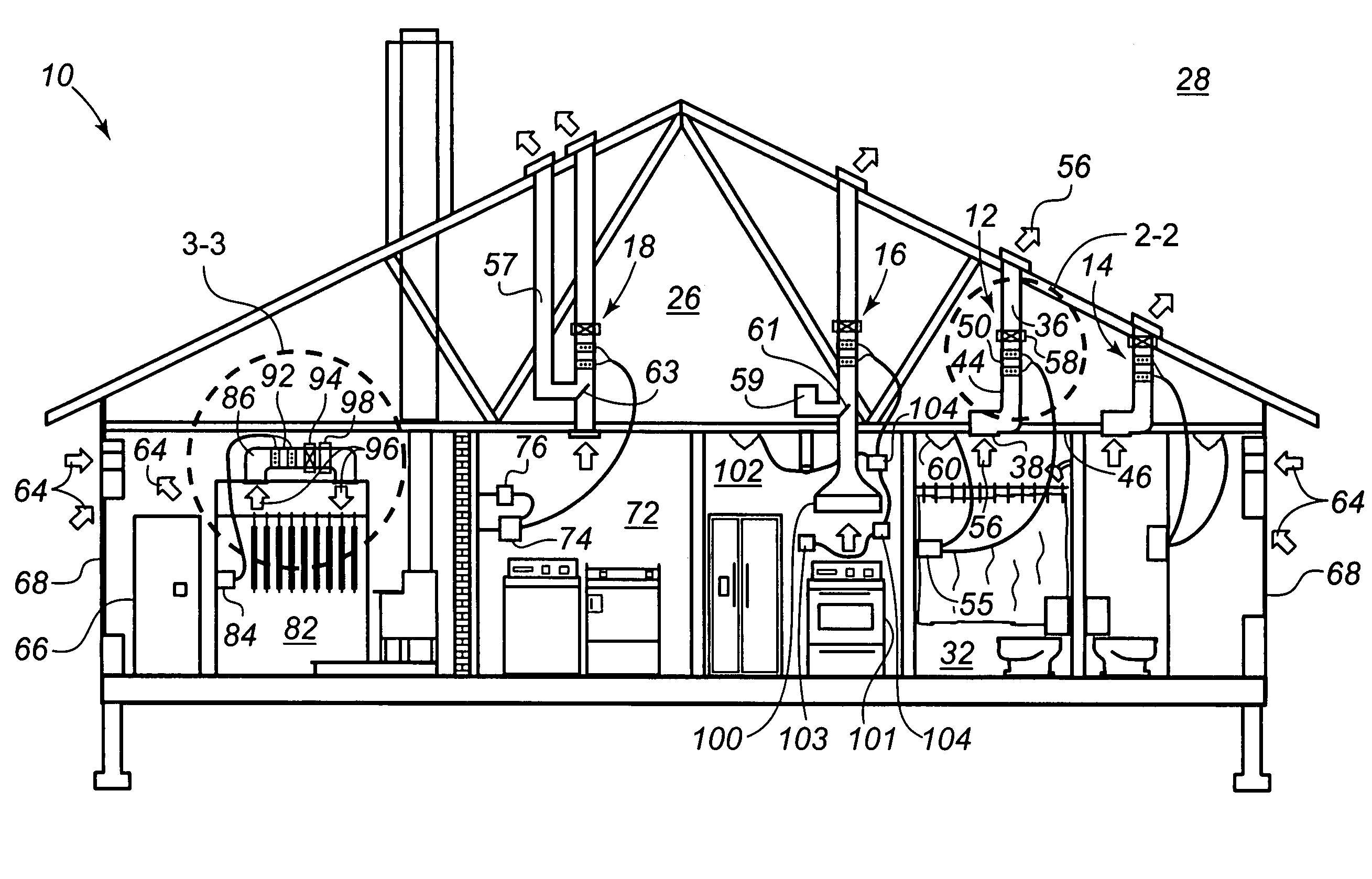
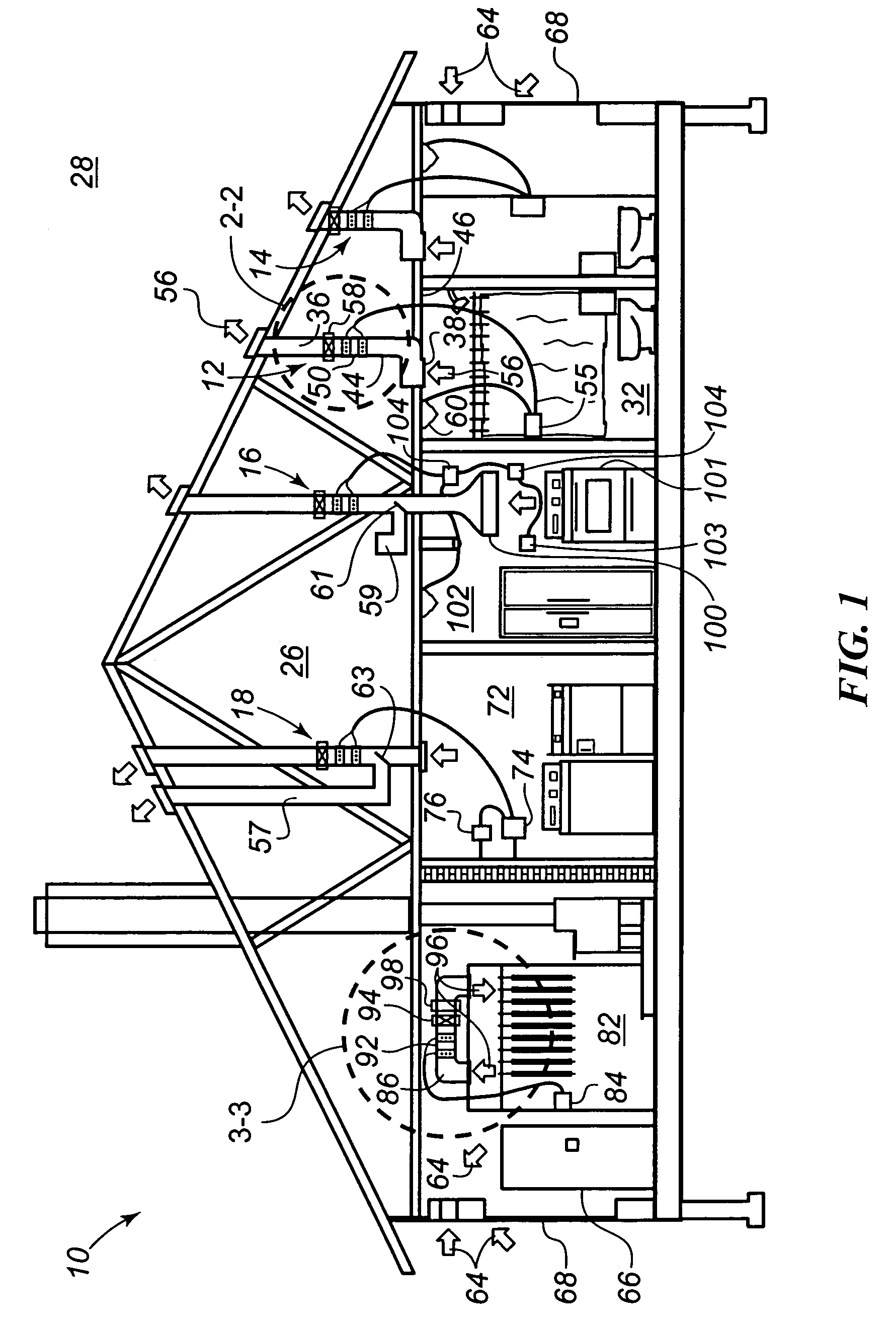
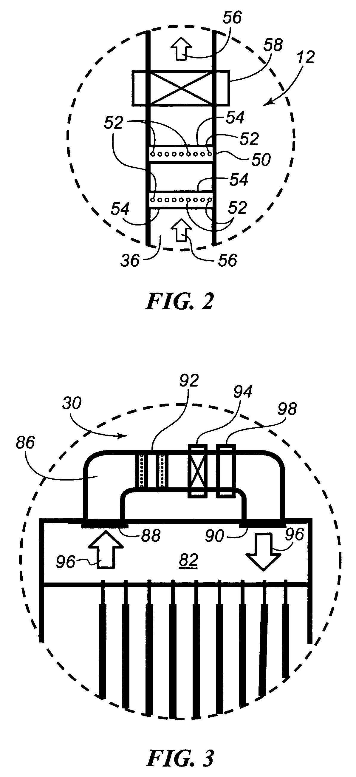
[0021]Referring to FIG. 1, a building 10 incorporating numerous spot ventilators according to the present invention is illustrated. Particularly, the building 10 incorporates numerous spot ventilators 12, 14, 16, 18 for selectively exhausting air from the interior 26 of the building 10 to the exterior 28 of the building 10. The building 10 further incorporates a spot ventilator 30 according to the present invention that selectively recirculates and filters the air within the interior 26 of the building 10. The drawings are illustrative in nature and should not be interpreted to restrict the design of the spot ventilators to any specific size, shape, form or configuration.

[0022]In an embodiment of the present invention, the spot ventilator 12 is associated with a bathroom 32 of the building 10. The spot ventilator 12 includes a passage 36 extending between an inlet 38 and an outlet 40. The passage 36 provides fluid communication between the interior 26 and exterior 28 of the building...


PUM

PropertyMeasurementUnit
humidityaaaaaaaaaa
polarityaaaaaaaaaa
humidityaaaaaaaaaa

Abstract

A spot ventilator and method for spot ventilating a localized environment of a building is provided. The spot ventilator includes a passage and at least one corona discharge apparatus. The passage extending between an inlet positioned in the localized environment and an outlet. The at least one corona discharge apparatus positioned in relation to the passage such that a fluid from the localized environment is drawn into the passage through the inlet and is expelled through the outlet. The method of ventilating a localized environment of a building includes the steps of sensing a first change in the localized environment, energizing a corona discharge apparatus to produce an electric wind, drawing air from the localized environment into a passage via the electric wind and expelling the air from the passage through the outlet.

Description

CROSS-REFERENCE TO RELATED PATENT APPLICATIONS[0001]This patent application claims the benefit of U.S. Provisional Patent Application No. 60 / 632,225, filed Nov. 30, 2004, the teachings and disclosure of which are hereby incorporated in their entireties by reference thereto.FIELD OF THE INVENTION[0002]This present invention relates generally to ventilation systems, and more particularly to spot ventilation systems for use in bathrooms, kitchens and closets.BACKGROUND OF THE INVENTION[0003]Traditional bathroom and kitchen ventilation systems may be classified generally as spot ventilation systems or spot ventilators, which are localized ventilation systems that remove pollutants quickly from their source as they are generated. They can be used whether or not a whole house ventilation system or natural ventilation system is used to substantially improve air quality.[0004]These spot ventilators are typically either a ducted ventilator or a recirculating ventilator. In each type of venti...

Claims


Application Information

Patent Timeline
Patent Type & Authority Patents(United States)
IPC IPC(8): B03C3/68
CPCB01D53/32B03C3/011B03C3/017B03C2201/14
Inventor EHLERS, GREGORY ALLEN
Owner RANCO OF DELAWARE
Why Eureka
Try Eureka