Precision Rogowski coil and method for manufacturing same

a technology of rogowski coils and coils, which is applied in the direction of instruments, discontinuously variable inductance/transformers, inductances, etc., can solve the problems of reducing coil densities, inadequate external field cancellation means, and design less suitable for low frequency current measurement applications

Inactive Publication Date: 2007-06-05
SCHWEITZER ENGINEERING LABORATORIES
View PDF49 Cites 78 Cited by
  • Summary
  • Abstract
  • Description
  • Claims
  • Application Information

AI Technical Summary

Problems solved by technology

While high sensitivity is very desirable when measuring low frequency currents (50 / 60 Hz power system related), the patent fails to provide adequate means for external field cancellation.
This problem is reported in U.S. Pat. No. 6,624,624 and is caused by inadequate handling of the coil return path.
A similar problem applies to the design reported in U.S. Pat. No. 6,313,623 (by Kojovic, et al.) in which two closely spaced coils with counter rotation are used to perform partial return path compensation.
Attempts to provide improved return path cancellation resulted in significantly reduced coil densities, making the design less appropriate for low frequency current measurement applications.
In addition, although significantly improved, all reported geometries suffer from Z-axis (board thickness) related sensitivity contour effects with an error cancellation (return) path normally offset in the direction of the Z-axis (board thickness).

Method used


Image

  • Precision Rogowski coil and method for manufacturing same
  • Precision Rogowski coil and method for manufacturing same
  • Precision Rogowski coil and method for manufacturing same

Examples


Embodiment Construction

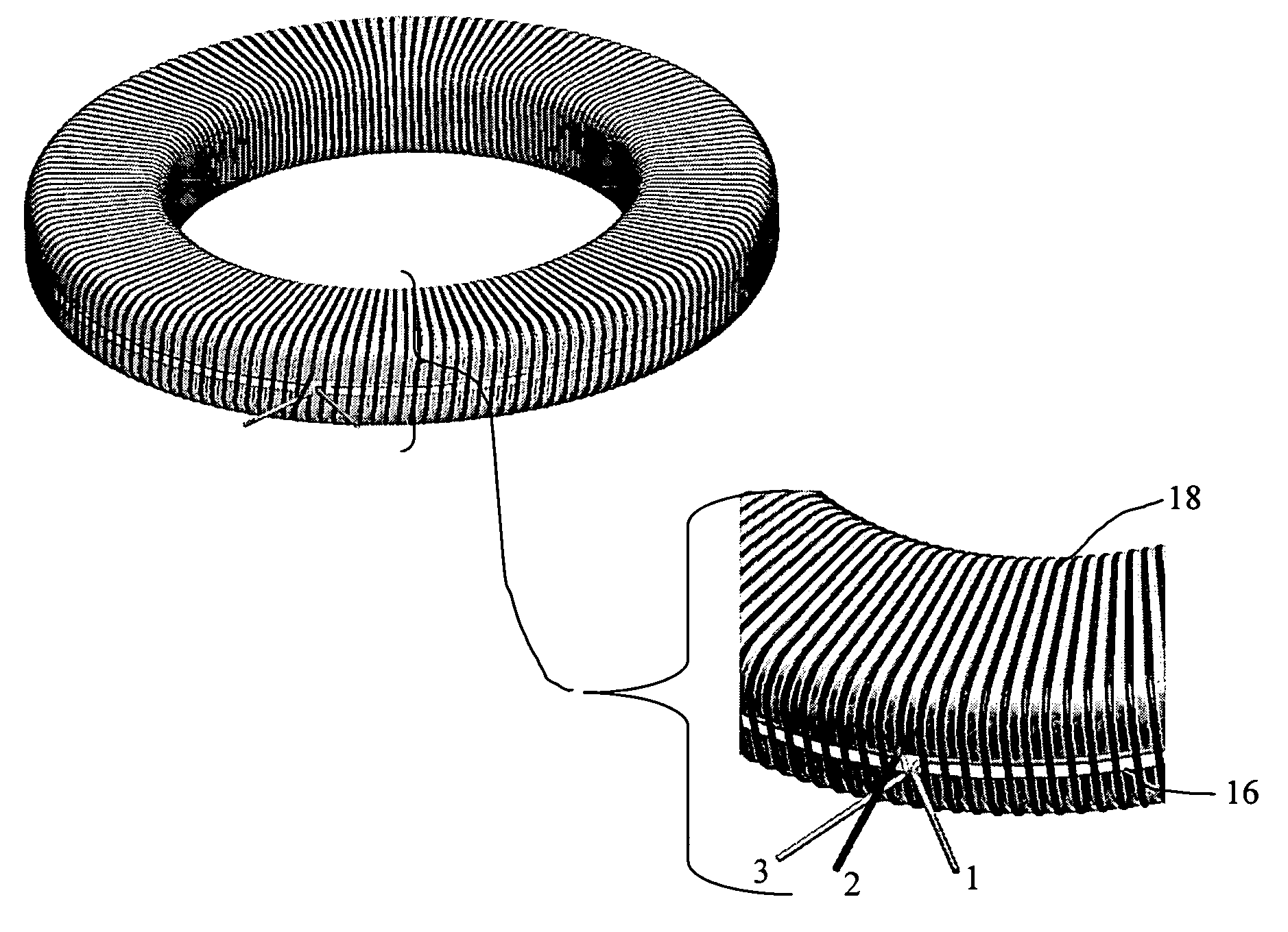
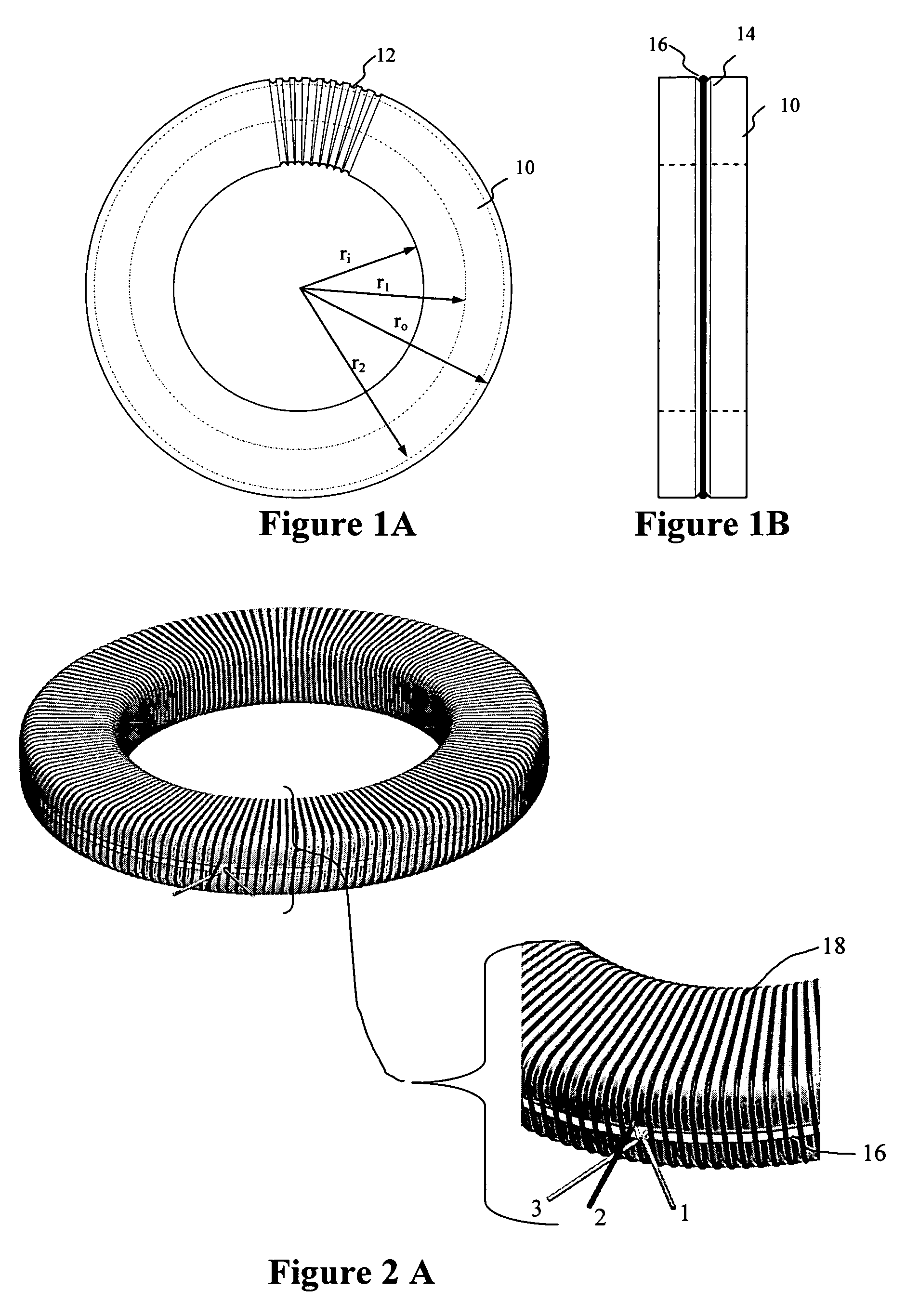
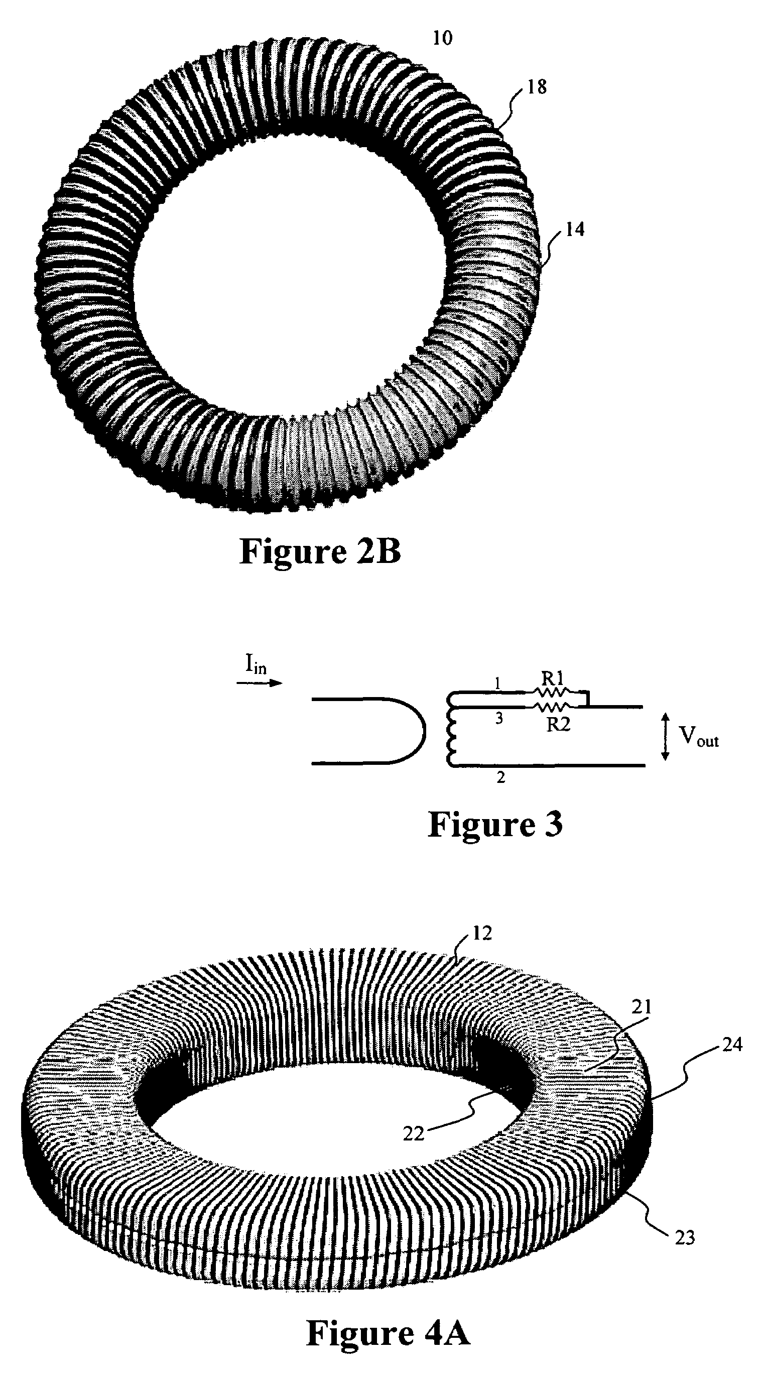
[0023]FIG. 1A illustrates a core 10 shaped generally as a toroid. The term “toroid” often connotes a “doughnut” shape but the present invention does not require a “doughnut” shape for the core 10. It will be understood from the illustrative drawings and the present description that a cross section cut through a diameter or radius of core 10 can be either circular, substantially rectangular, or otherwise, e.g. oval, oblong, or some other shape. That is, core 10 may have the geometric shape of a solid formed by rotating (orbiting) a closed form, be it a circle, square, rectangle, oval, oblong, or irregular shaped closed line, around 360 degrees of a circle. Thus, FIG. 2A shows a Rogowski coil according to certain aspects of the present invention where the core has generally “flattened” faces (like an annulus), which (but for the grooving) could be formed geometrically by rotating a rectangle with rounded corners around 360 degrees of a circle. FIG. 2B on the other hand shows another c...


PUM

PropertyMeasurementUnit
temperatureaaaaaaaaaa
diameteraaaaaaaaaa
diameteraaaaaaaaaa

Abstract

An improved Rogowski coil is formed on a toroidal core made of a thermoplastic or other moldable material, the core having a preferably continuous groove or grooves extending around the core. The grooves correspond in size to magnet wire which registers within the grooves, thus controlling the specific location of the wires. The grooving may be helical. A return loop can be provided for return path cancellation, or a reverse winding can be added in a direction opposite to the direction of advancement of the main coil. In using the return loop, a resistive network can be added to improve the cancellation of the return path due to the effect of geometries. In addition, it can compensate for thermal and other variations.

Description

BACKGROUND OF THE INVENTION[0001]The present invention concerns Rogowski coils. More particularly, the present invention concerns the structure and manner of making a Rogowski coil.[0002]Rogowski coils are well known electrical devices finding use today for measurement of magnetic fields and electrical currents. They have been researched over the past century and are well known to the scientific literature. Their origin traces to the invention circa 1912 of the Rogowski coil by W. Rogowski and W. Steinhousen. The device is useful for measuring electrical currents and operates on the basis of a magnetic field integration performed across a closed contour being equal to the current flowing through the contour. The coil provides a voltage output proportional to the time derivative of the current (di / dt) rather than a current output like other current transformers.[0003]Rogowski coils are popular because of their dynamic range and linearity. However, though theoretical requirements are ...

Claims


Application Information

Patent Timeline
Patent Type & Authority Patents(United States)
IPC IPC(8): H01F5/00
CPCH01F5/003G01R15/181H01F17/0033Y10T29/49071H01F27/40Y10T29/4902H01F21/12
Inventor SKENDZIC, VESELINKESLER, JAMES R.
Owner SCHWEITZER ENGINEERING LABORATORIES
Why Eureka
Try Eureka