
Motorized barrier operator system utilizing multiple photo-eye safety system and methods for installing and using the same

Inactive Publication Date: 2007-06-12
WAYNE DALTON CORP
View PDF14 Cites 23 Cited by
  • Summary
  • Abstract
  • Description
  • Claims
  • Application Information

AI Technical Summary

Benefits of technology

[0015]It is thus an object of the present invention to provide a motorized barrier operator sy

Problems solved by technology

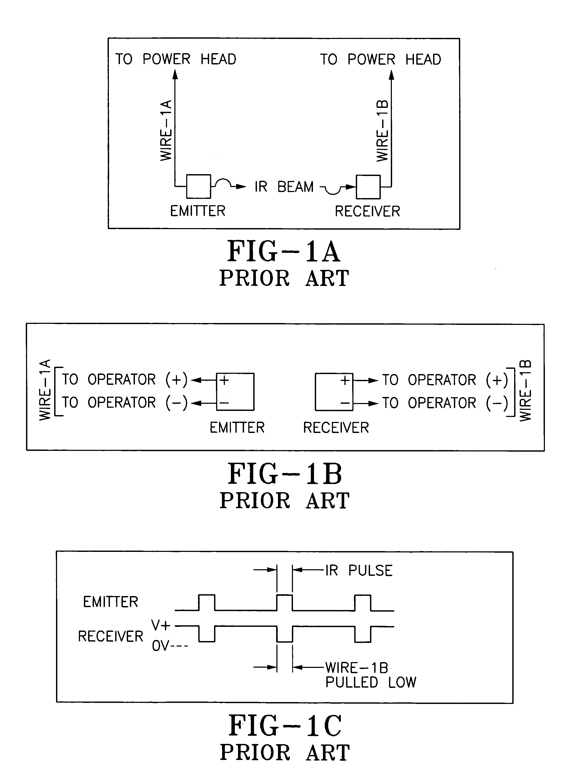
But, one issue consumers have with this arrangement is that the IR beam can shoot under a vehicle if it is parked only half-way into the garage.
But the door striking the vehicle can cause damage to the vehicle's surface.
But, mounting the photo eyes greater than 6 inches off of the floor creates a hazard since the photo eyes are unable to detect a child laying on the floor.
Several patents disclose various safety and photo-eye configurations, but none appear to directly address the problem of photo-eye height adjustment undertaken by the end user.
Failure to receive the active safety signal when the motor is closing the door at least stops the door.
As will be appreciated from a review of the above patents, none appreciate the problem associated with the end-user surreptitiously moving the photo-eye set from the intended location.

Method used


Image

  • Motorized barrier operator system utilizing multiple photo-eye safety system and methods for installing and using the same
  • Motorized barrier operator system utilizing multiple photo-eye safety system and methods for installing and using the same
  • Motorized barrier operator system utilizing multiple photo-eye safety system and methods for installing and using the same

Examples


Embodiment Construction

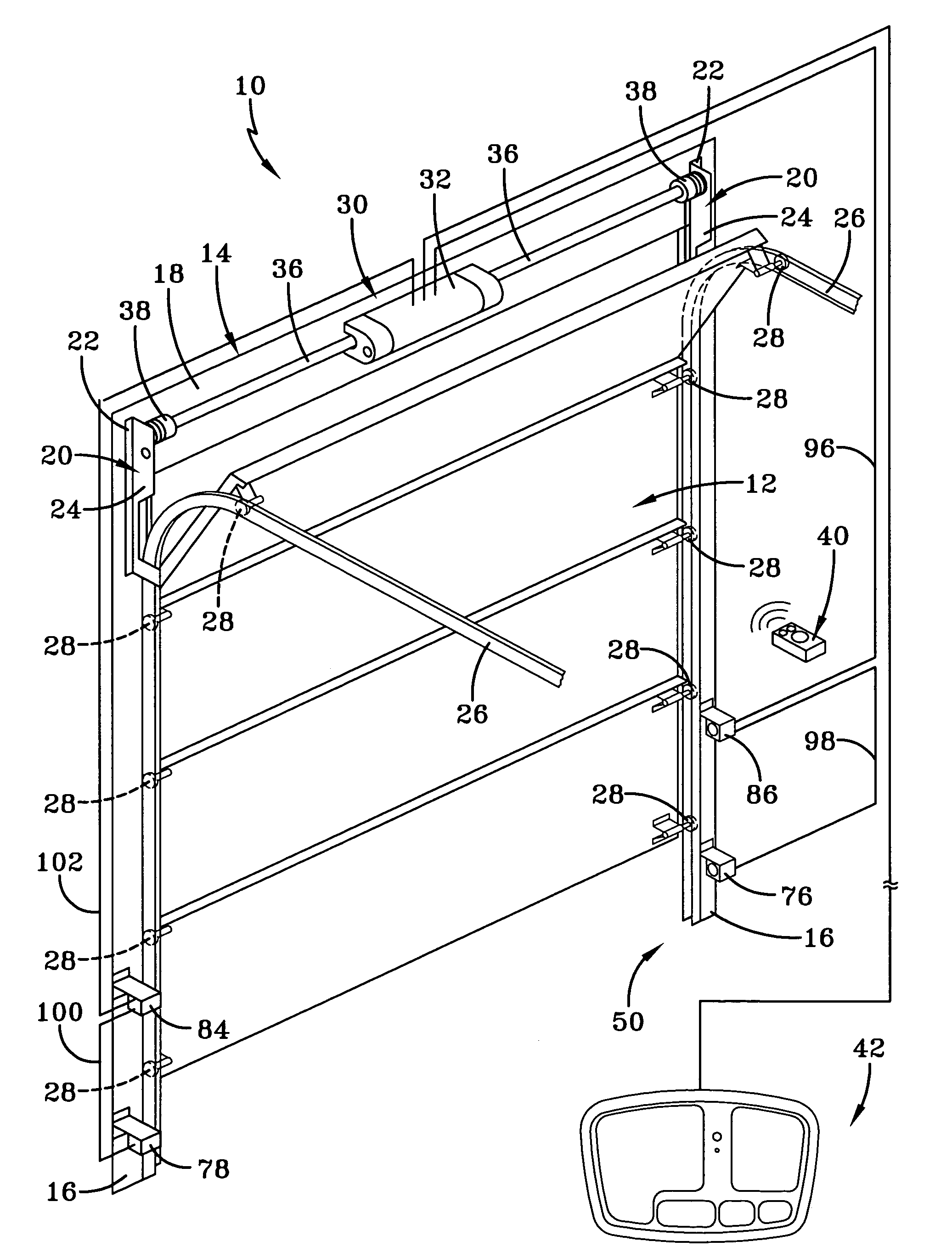
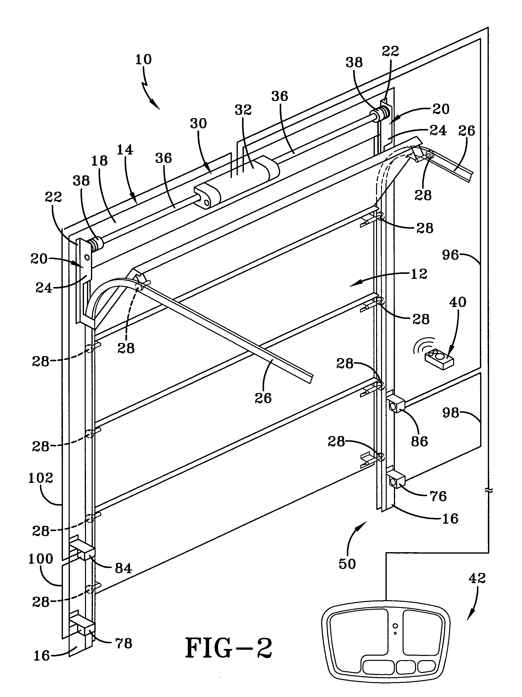
[0027]A motorized barrier operator adaptable to different safety configurations is generally indicated by the numeral 10 in FIG. 2 of the drawings. The system 10 is employed in conjunction with a conventional sectional garage barrier or door generally indicated by the numeral 12. The teachings of the present invention are equally applicable to other types of movable barriers such as single panel doors, gates, windows, retractable overhangs, and any device that at least partially encloses an area. The door 12 is most likely an anti-pinch type door. The opening in which the door is positioned for opening and closing movements relative thereto is surrounded by a frame, generally indicated by the numeral 14, which consists of a pair of vertically spaced jamb members 16 that, as seen in FIG. 1, are generally parallel and extend vertically upward from the ground (not shown). The jambs 16 are spaced and joined at their vertical upper extremity by a header 18 to thereby form a generally u-s...


PUM


Abstract

A movable barrier operator system includes a motorized operator which moves a barrier between limit positions, and a photo-electric safety system connected to the motorized operator. The photo-electric safety system monitors for obstructions at more than one height along the barrier's path between limit positions. This is done by installing a supplemental photo-electric safety system to work in conjunction with a pre-existing photo-electric safety system connected to the motorized barrier operator.

Description

TECHNICAL FIELD[0001]Generally, the present invention relates to a movable barrier operator system for use on a closure member moveable relative to a fixed member. More particularly, the present invention relates to an operator-controlled motor for controlling the operation of a closure member, such as a gate or door, between a closed position and an open position. More specifically, the present invention relates to a barrier operator, wherein the operator utilizes multiple photo-eyes to detect obstructions at different heights.BACKGROUND ART[0002]For convenience purposes, it is well known to provide garage doors which utilize a motor to provide opening and closing movements of the door. Motors may also be coupled with other types of movable barriers such as gates, windows, retractable overhangs and the like. An operator is employed to control the motor and related functions with respect to the door. The operator receives command signals for the purpose of opening and closing the do...

Claims


Application Information

Patent Timeline
IPC IPC(8): E05D15/00E05F15/00H02P1/04
CPCE05F15/43E05F15/668E05Y2400/822E05Y2600/45E05Y2800/21E05F2015/436E05F15/00E05Y2900/106
Inventor MURRAY, JAMES S
Owner WAYNE DALTON CORP
Learn More