Method to detect misalignment and distortion in near-eye displays

a near-eye display and misalignment technology, applied in the field of binocular devices, can solve the problems of eye strain or other severe symptoms, the hmd does not fit well, and the binocular instruments have slight differences between the two images, so as to reduce the adverse effects of symptoms

Inactive Publication Date: 2007-06-12
INTELLECTUAL VENTURES I LLC
View PDF6 Cites 7 Cited by
  • Summary
  • Abstract
  • Description
  • Claims
  • Application Information

AI Technical Summary

Benefits of technology

[0007]It is a primary object of the present invention to provide a method and system for correcting the misalignments in a binocular device so as to reduce adverse symptoms due to the misalignments.

Problems solved by technology

However, all binocular instruments have slight differences between the two images.
One possibility is that the HMD does not fit well and for this reason the displays are not directly in front of the left and right eyes.
This means that the eyes are forced to align themselves in an unnatural way, which may cause eyestrain or other severe symptoms.
This would cause eyestrain.
This eye movement also strains the muscular systems that support the movements.
Misalignment in optical components relative to the eyes can cause image distortion.
Optical effects such as towel distortion, rotations, translations and so forth may cause further eyestrains in difficulties in perceiving the image.
Small misalignment or distortions is unnoticeable and may be tolerable, but when misalignment or distortion increases, extended use can cause severe headache.
Very large differences between left and right images can cause eyestrain, nausea and headache.
These methods can only detect global misalignment.
They are unable to detect local differences or complex distortions.
In practice, localized alignments based on local differences are not useful because the visual system is not sensitive enough for such procedures.
For example, it cannot make measurements in both horizontal and vertical directions at the same time.
This method is not flexible and also time-consuming.

Method used


Image

  • Method to detect misalignment and distortion in near-eye displays
  • Method to detect misalignment and distortion in near-eye displays
  • Method to detect misalignment and distortion in near-eye displays

Examples


Embodiment Construction

[0030]The invention is based on three processes of the visual system.

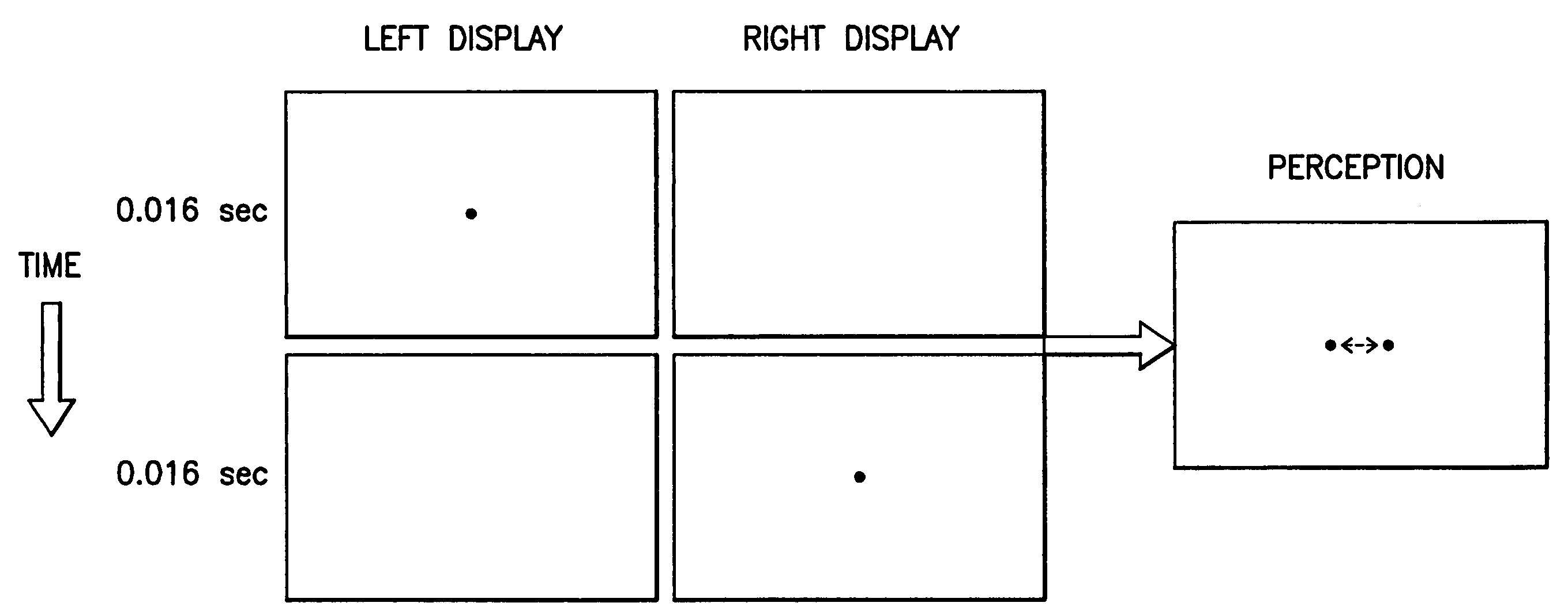
[0031]1. Apparent movement means that if two dots are alternately flashed in a sufficient frequency and from some distance apart, there appears an illusion of movement between these two dots. For example television and movies are based on this illusion: although the broadcast or show consists of separate static frames, they are perceived as a smooth movement because they are shown fast enough sequence.

[0032]2. Interocular apparent movement means that you can show the dots or frames alternately to left and right eye and still see the illusion of movement.

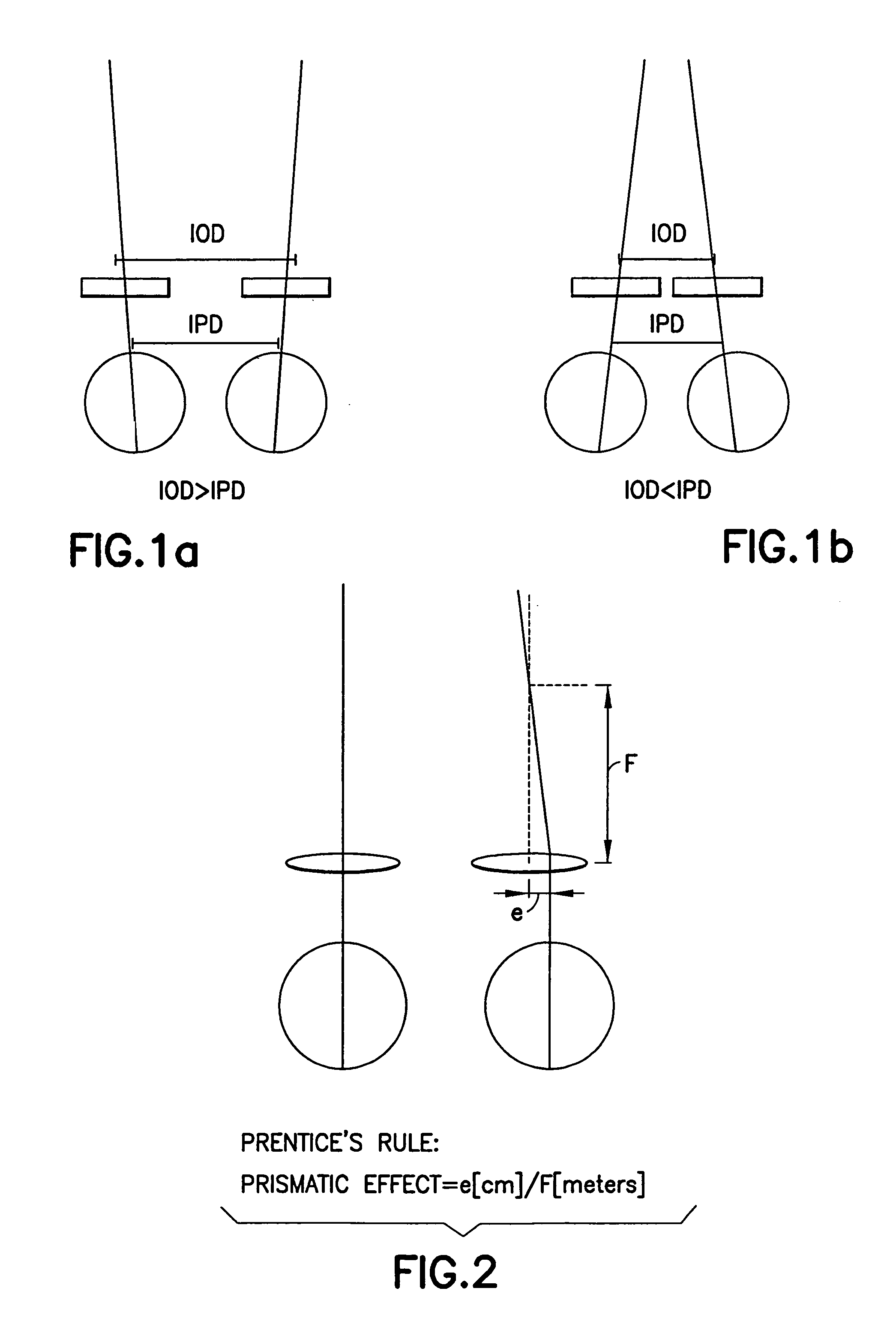
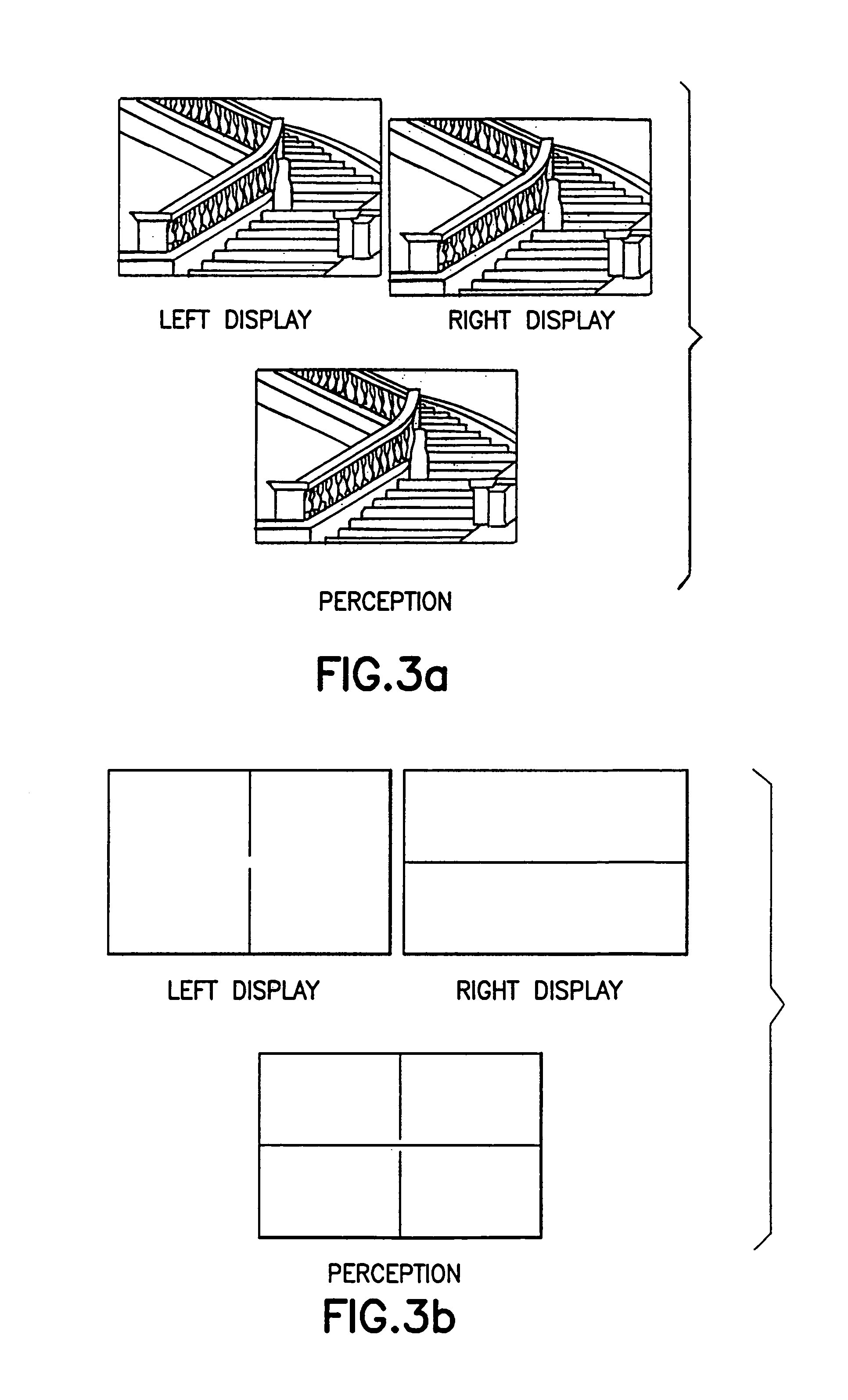
[0033]3. Stereoscopic fusion means that the visual system has to fuse the images relayed from left and right eye to form a single three-dimensional perception of world that we usually experience. The fusion is possible even if the images are highly artificial, as in a HMD. Although the fusion is achieved in the case of the HMD, the eye muscles have to work hard to m...


PUM


Abstract

A flashing dot is alternately shown in the left image and right display of a binocular device at short intervals so as to allow a user to detect the misalignment in the displays. If misalignment occurs, the user sees a dot moving between two locations. The user uses a device or a software program to move the dot for minimizing the apparent movement until a single stationary dot is observed.

Description

[0001]This application is based on and claims priority of U.S. Provisional application No. 60 / 368,627, filed Mar. 28, 2002.FIELD OF THE INVENTION[0002]The present invention relates to a binocular device and, more specifically, to a binocular near-eye display.BACKGROUND OF THE INVENTION[0003]If a binocular or biocular HMD (head-mounted display or helmet-mounted display) is well constructed and aligned, only one scene is perceived and viewing is comfortable. However, all binocular instruments have slight differences between the two images. The differences in image geometry may have many different causes. One possibility is that the HMD does not fit well and for this reason the displays are not directly in front of the left and right eyes. This means that the eyes are forced to align themselves in an unnatural way, which may cause eyestrain or other severe symptoms. For example, if the interocular distance (IOD) is larger than the interpupillary distance (IPD), the eyes have to turn to...

Claims


Application Information

Patent Timeline
Patent Type & Authority Patents(United States)
IPC IPC(8): A61B3/10G02B7/12G02B27/00G02B27/01
CPCG02B7/12G02B27/017G02B27/0172G02B2027/0132
Inventor HAKKINEN, JUKKA
Owner INTELLECTUAL VENTURES I LLC
Why Eureka
Try Eureka