Scroll compressor having an annular recess located outside an annular seal portion and another recess communicating with suction port of fixed scroll

a compressor and annular recess technology, applied in the direction of machines/engines, rotary/oscillating piston pump components, liquid fuel engines, etc., can solve the problems of increasing the accelerating the turning-over phenomenon of the orbiting scroll under low pressure compression ratio operation, and prone to unbalance between the compression chambers. to be generated, to prevent the effect of sliding loss from being increased, and excessively high back pressure of the orbiting scroll

Active Publication Date: 2007-06-12
PANASONIC CORP
View PDF8 Cites 59 Cited by
  • Summary
  • Abstract
  • Description
  • Claims
  • Application Information

AI Technical Summary

Benefits of technology

[0009]Conventionally, high pressure, or medium pressure between high pressure and low pressure is applied to the recess for applying back pressure. According to this first aspect, low pressure suction pressure is applied to the recess, an area corresponding to the recess is applied in a direction in which the back pressure of the orbiting scroll is increased, and the turning-over phenomenon of the orbiting scroll can be suppressed even under the operation condition in which there is a tendency that the back pressure is reduced under a low pressure compression ratio operation. Since the recess is formed, necessary substantially annular seal portion is secured, the sliding area at the thrust portion can be reduced and thus, sliding loss can be reduced, compression efficiency can be enhanced under low pressure compression ratio operation, mechanical efficiency and reliability can be enhanced under high-pressure compression ratio operation.
[0027]According to this aspect, it is possible to prevent sliding loss from being increased also in a scroll compressor in which the back pressure of the orbiting scroll is excessively great and there is a tendency that the sliding loss at the thrust sliding portion is increased. In a heat pump water heating system using carbon dioxide as refrigerant, the scroll compressor is operated with extremely low compression ratio in some cases due to characteristics of the system, and it is possible to provide an efficient scroll compressor even under such a using condition.

Problems solved by technology

In such a case, pressure unbalance between the compression chambers is prone to be generated, and there is an adverse possibility that the turning-over phenomenon of the orbiting scroll under low pressure compression ratio operation is accelerated.

Method used


Image

  • Scroll compressor having an annular recess located outside an annular seal portion and another recess communicating with suction port of fixed scroll
  • Scroll compressor having an annular recess located outside an annular seal portion and another recess communicating with suction port of fixed scroll
  • Scroll compressor having an annular recess located outside an annular seal portion and another recess communicating with suction port of fixed scroll

Examples


first embodiment

[0034](First Embodiment)

[0035]Embodiments of the present invention will be explained with reference to the drawings. It should be noted that the invention is not limited by the embodiments.

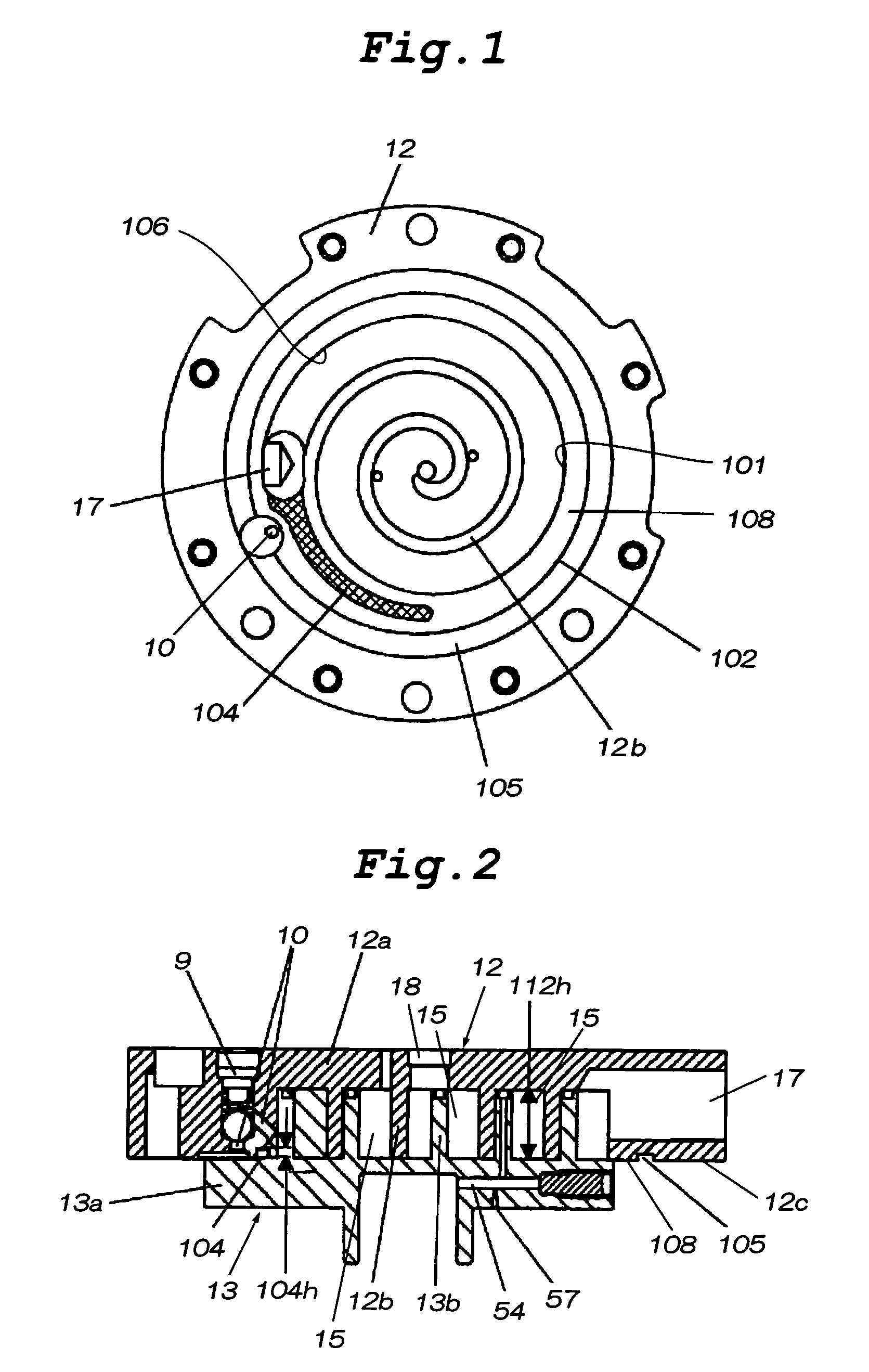
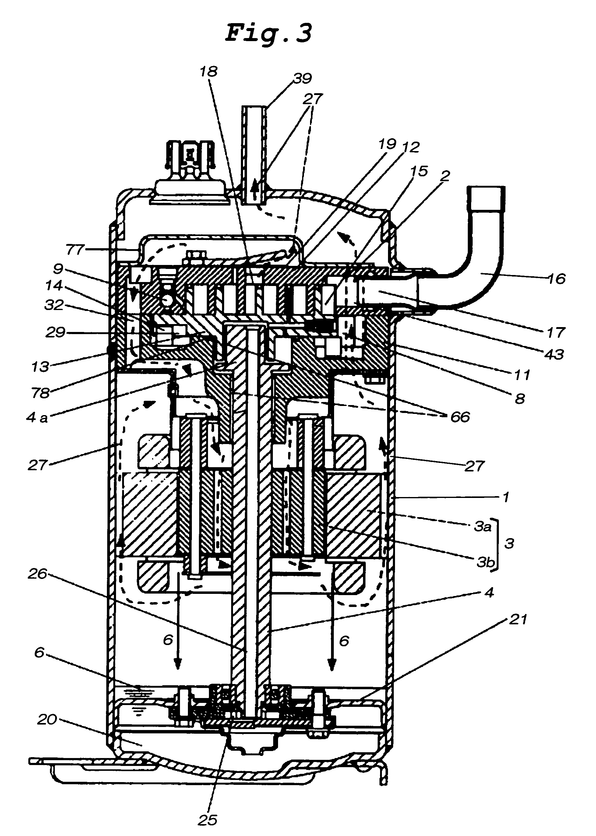
[0036]FIG. 1 is a plan view of a fixed scroll which is an essential portion of a scroll compressor of a first embodiment of the present invention, FIG. 2 is an enlarged vertical sectional view of the scroll compressor shown in FIG. 1, and FIG. 3 is a vertical sectional view of the scroll compressor of the first embodiment of the invention.

[0037]In FIGS. 1 and 2, in the scroll compressor of this embodiment, a fixed scroll 12 has a scroll lap 12b, and an orbiting scroll 13 located on the outer side of the scroll lap 12b has a end plate 13a. A surface of the fixed scroll 12 opposed to the end plate 13a is formed with a substantially annular seal portion 108, a substantially annular recess 105 located outward of the substantially annular seal portion 108, and a recess 104 (meshed portion in FIG. 1) wh...

second embodiment

[0055](Second Embodiment)

[0056]A scroll compressor of a second embodiment of the present invention will be explained using FIGS. 1 and 2.

[0057]According to the scroll compressor of this embodiment, the lap 12b of the fixed scroll 12 extends from its winding terminal end to a winding terminal end area of a lap 13b of the orbiting scroll 13, and an inner wall surface of an extension of the lap 12b is formed of curve 106 which is continuous with the lap 12b of the fixed scroll 12.

[0058]In the case of the scroll compressor of this embodiment, the extension can be used as a passage of the suction stroke or can be used as a portion of the compression stroke. In an example of the latter case, a gap in the vicinity of the continuous curve 106 and the winding terminal of the lap 13b of the orbiting scroll 13 is set to a very small value, and the scroll compressor is operated while changing the capacity of the compression chamber 15 in a pseudo manner in accordance with the operation speed of...

third embodiment

[0063](Third Embodiment)

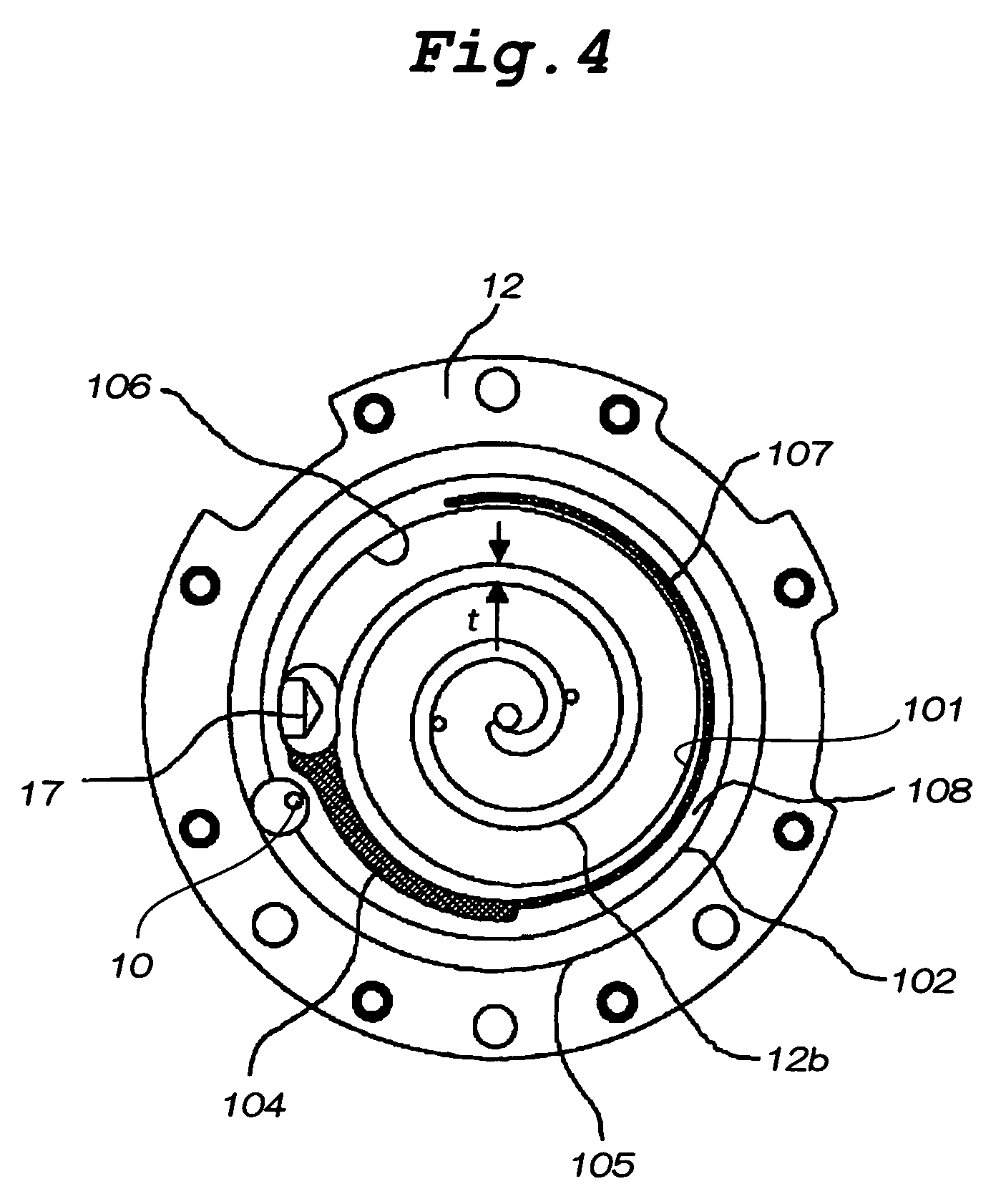
[0064]A scroll compressor of a third embodiment of the present invention will be explained. FIG. 4 is a plan view of a fixed scroll which is an essential portion of the scroll compressor of the third embodiment of the invention.

[0065]As shown in FIG. 4, according to the scroll compressor of this embodiment, the substantially annular seal portion 108 is provided with a thin groove 107 extending to a location in the vicinity of the winding terminal end of the lap 13b of the orbiting scroll 13, and the thin groove 107 is brought into communication with a recess 104 which is in communication with the intake port 17. That is, suction pressure is applied to the thin groove 107, and suction pressure enters from a most angle range of the substantially annular seal portion 108.

[0066]Therefore, according to the scroll compressor of this embodiment, suction pressure can be applied to most portion of the end plate 13a of the orbiting scroll 13, back pressure application ...


PUM


Abstract

A surface of a fixed scroll which is opposed to a end plate of an orbiting scroll existing outside of a lap of the fixed scroll is formed with: a substantially annular seal portion which extends such as to have an outer wall surface of the fixed scroll outwardly extending from an inner wall surface of outermost periphery of the lap substantially along the inner wall surface, and which comes into slide contact with the end plate of the orbiting scroll; a substantially annular recess located outside of the substantially annular seal portion; and a recess which is brought into communication with an intake port of the fixed scroll independently from the substantially annular recess. With this, back pressure of the orbiting scroll is increased, and turning-over phenomenon of the orbiting scroll can be suppressed.

Description

TECHNICAL FIELD[0001]The present invention relates to a scroll compressor used for a business type, domestic type or vehicular freezer air conditioner, or for a heat pump type water heating system.BACKGROUND TECHNIQUE[0002]In conventional scroll compressors of this type, opposed surfaces of a fixed scroll and a end plate of an orbiting scroll are provided with an annular seal portion and an annular recess located outside of this seal portion (see patent document 1 for example).[0003]FIG. 6 shows the conventional scroll compressor described in the patent document 1. As shown in FIG. 6, a fixed scroll 202 has a scroll lap 221b, and an orbiting scroll (not shown) existing on an outer side of the scroll lap 221b has a end plate. An annular seal portion 213 and an annular recess 214 are formed in a surface of the fixed scroll 202 opposed to the end plate. The seal portion 213 extends such as to have an outer wall surface 221c which extends from inner wall surfaces 215a to 215d of outermo...

Claims


Application Information

Patent Timeline
Patent Type & Authority Patents(United States)
IPC IPC(8): F03C2/00F04C18/00F04CF04C18/02F04C27/00F04C29/00
CPCF04C27/005F04C29/0021F04C18/0215F04C18/02
Inventor MORIMOTO, TAKASHIFUTAGAMI, YOSHIYUKIHIWATA, AKIRATSUJIMOTO, TSUTOMU
Owner PANASONIC CORP
Why Eureka
Try Eureka