Ultrasonic calculus treatment apparatus

a calculus treatment and ultrasonic technology, applied in the field of surgical equipment using an ultrasonic transducer, can solve the problems of long treatment time, calculus may not be completely and efficiently shattered, and may not be easily removed from the body

Inactive Publication Date: 2007-06-12
OLYMPUS CORP
View PDF17 Cites 364 Cited by
  • Summary
  • Abstract
  • Description
  • Claims
  • Application Information

AI Technical Summary

Benefits of technology

[0022]Accordingly, torsional vibration can be generated with enough amplitude at the distal end of the ultrasonic transmitting member so that treatment for calculus removal can be effectively performed by shattering the calculus.

Problems solved by technology

At this time, by only using the longitudinal vibration, the calculus may not be completely and efficiently shattered.
Accordingly, the calculus may not be easily removed from a body.
Thus, it may take long time for treatment.
However, the above-mentioned related art has a disadvantage in that the generation of the torsional vibration at the distal end of the probe is limited.
Due to the structure, such a problem that the amplitude of the longitudinal vibration cannot be obtained enough occurs, resulting in a deterioration in efficiency of disintegration of a calculus.
However, since means for freely changing and setting longitudinal vibration and torsional vibration is not disclosed, a function for effectively shattering a calculus may not be completed.

Method used


Image

  • Ultrasonic calculus treatment apparatus
  • Ultrasonic calculus treatment apparatus
  • Ultrasonic calculus treatment apparatus

Examples


first embodiment

[0043]A first embodiment according to the present invention will now be described with reference to FIGS. 1 to 10.

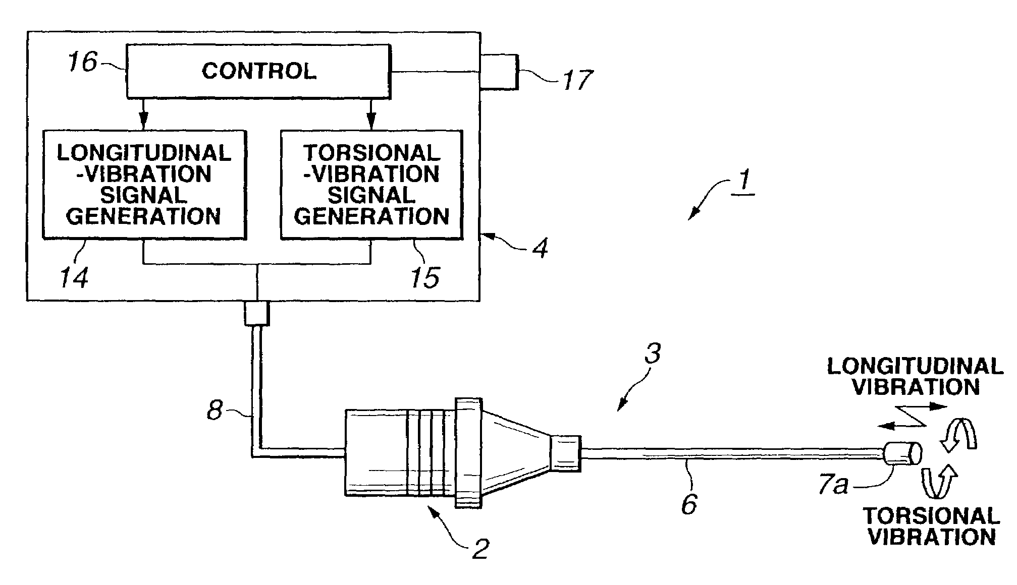
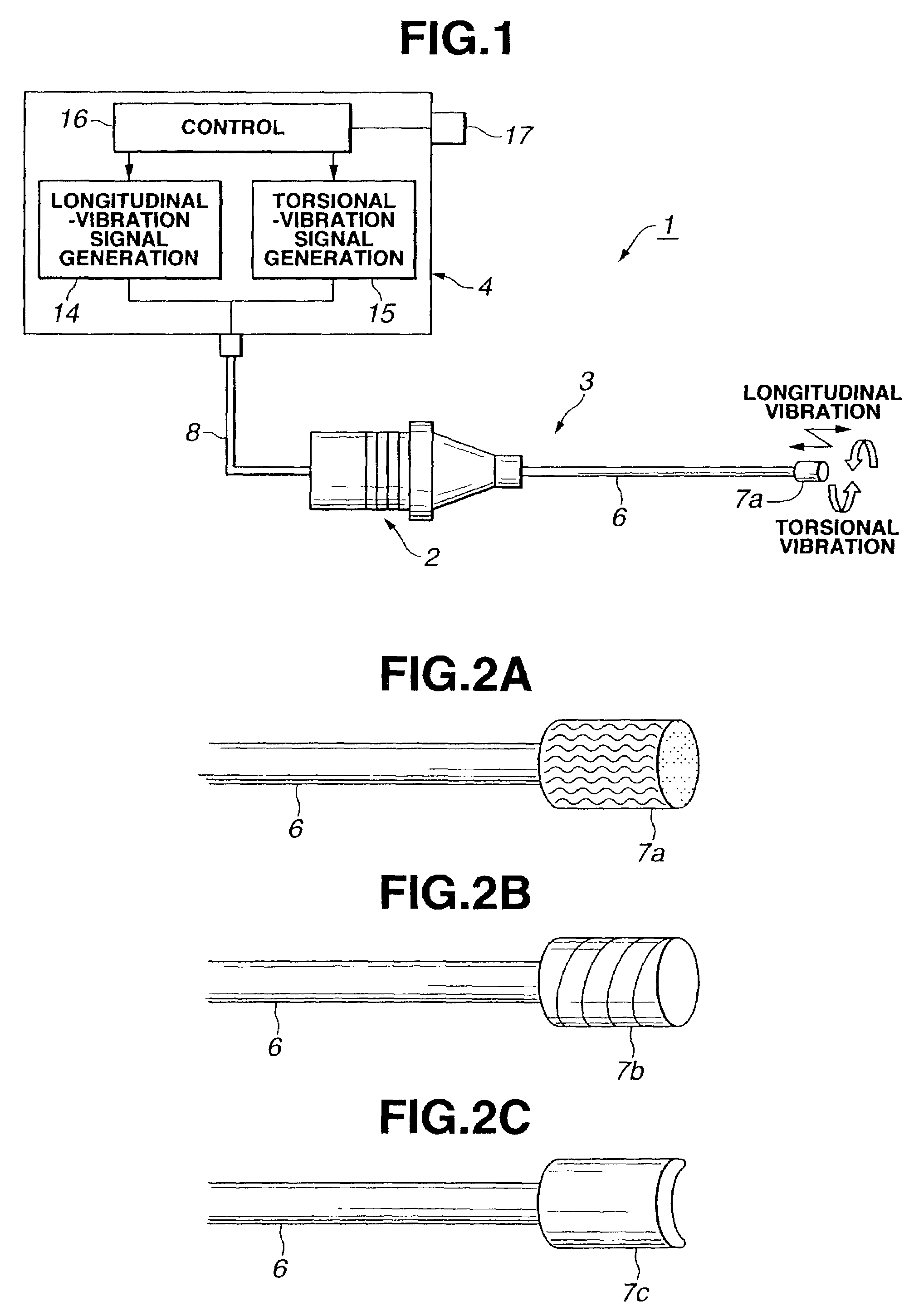
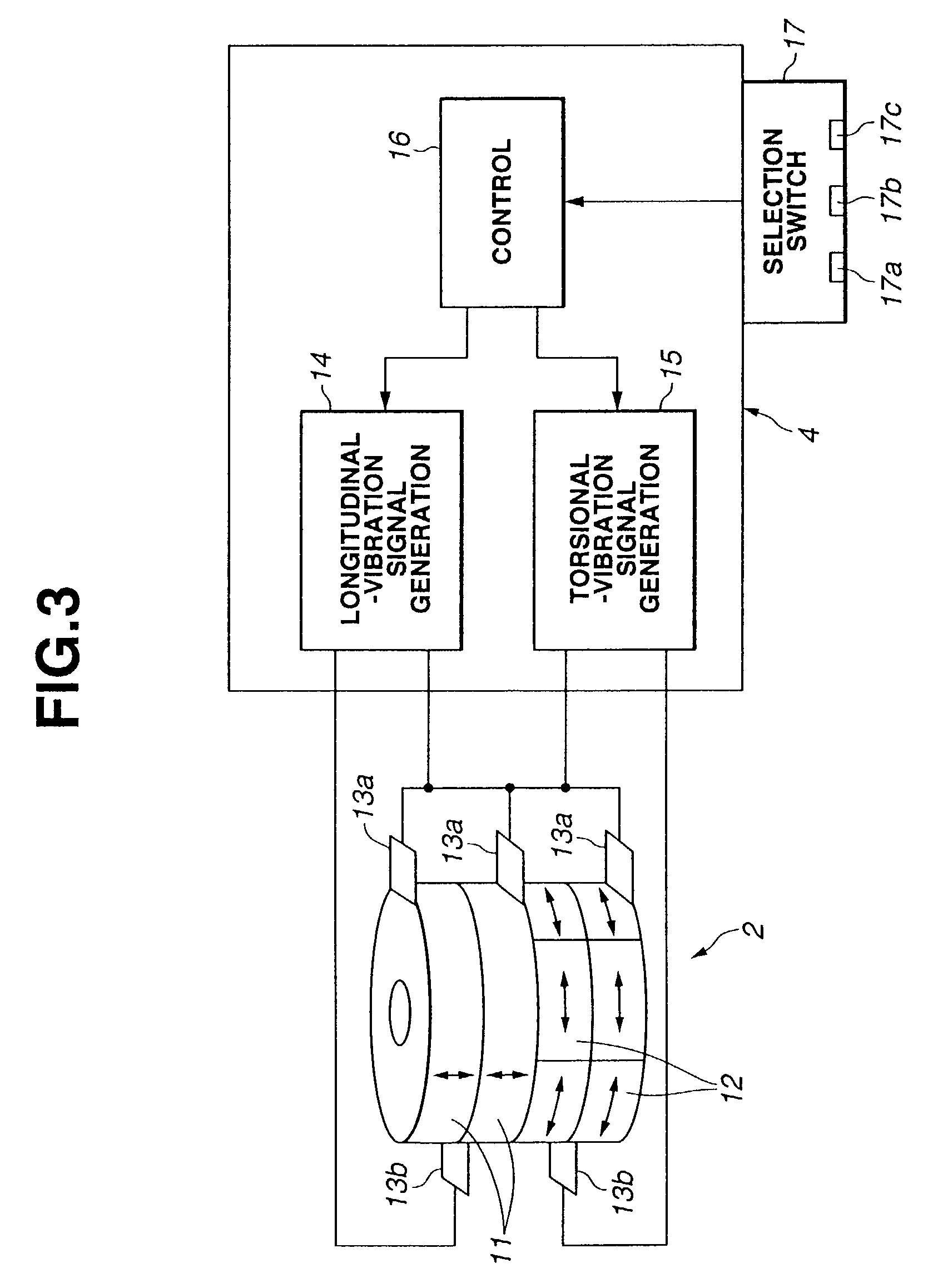
[0044]Referring to FIG. 1, according to the first embodiment of the present invention, an ultrasonic lithotriptor 1 comprises an ultrasonic transducer 2 for producing torsional vibration and longitudinal vibration, an ultrasonic lithotriptor main body (also called an apparatus main body) 3 including the ultrasonic transducer 2, and an ultrasonic driving signal generator (also called a signal generator) 4 for supplying a driving signal to produce ultrasonic waves to the apparatus main body 3. In FIG. 1, exterior components of the apparatus main body 3 are omitted.

[0045]The apparatus main body (also called a handpiece in an embodiment, which will be explained later) 3 has the ultrasonic transducer 2 disposed (in a grasping control section) at the rear end of the apparatus main body 3, a long vibration transmitting member 6, connected to the ultrasonic transducer 2, for tra...

second embodiment

[0108]the present invention will now be described with reference to FIGS. 11 to 13C.

[0109]FIG. 11 shows a handpiece 32 in an ultrasonic tissue coagulation incision apparatus having an ultrasonic vibrator 31 for producing torsional vibration therein.

[0110]The handpiece 32 comprises: a transducer 33 having the torsional vibrator 31; a handle 34 which is arranged near the transducer 33 and which an operator holds with their hand and then operates; a probe 36 serving as an ultrasonic transmitting member for transmitting ultrasonic vibration produced by the torsional vibrator 31 to an operating tool 35 at the distal end of the probe; a movable grasping tool 37 which comes into contact with or released from the end surface of the probe 36 by operating the handle 34; a coupling rod (not shown) for coupling the movable grasping tool 37 with the handle 34; and a sheath 38 covering the probe 36.

[0111]The transducer 33 is connected to a signal generator (not shown) for generating a driving sig...

third embodiment

[0123]An ultrasonic surgical instrument of the present invention will now be described. The ultrasonic surgical instrument has a characteristic ultrasonic driving signal generator.

[0124]An outline of the present embodiment will now be described. According to the present embodiment, a handpiece is first driven by a driving signal with a frequency generated by a variable frequency oscillator, and a phase difference between a voltage phase signal θV as the driving signal detected by a voltage and current detection circuit and an output signal from the variable frequency oscillator is checked.

[0125]When the phase difference is equivalent to 0°, the operation of the handpiece is switched so that the handpiece is driven by an output signal of a PLL which operates by comparing the phase of the voltage phase signal θV as the handpiece driving signal with the phase of a current phase signal θI, thereby tracking a resonance frequency. In this case, the variable frequency oscillator comprises ...


PUM


Abstract

An ultrasonic calculus treatment apparatus includes a longitudinal-vibration piezoelectric oscillator for vibrating in the axial direction of an ultrasonic transmitting member and a torsional-vibration piezoelectric oscillator for vibrating about the axial direction, and further includes driving circuits for driving the piezoelectric oscillators at respective resonance frequencies and a mode selection switch for permitting the oscillators to vibrate independently or in combination, so that lithotripsy can be performed effectively in accordance with the size of a calculus or a function of an operating tool.

Description

[0001]This application claims benefit of Japanese Application Nos. 2001-266251 and 2001-313013 filed on Sep. 3, 2001 and Oct. 10, 2001, respectively, the contents of which are incorporated by this reference.BACKGROUND OF THE INVENTION[0002]1. Field of the Invention[0003]The present invention relates to a surgical apparatus using an ultrasonic transducer and, more particularly to an ultrasonic calculus treatment apparatus for breaking a calculus into pieces to remove the calculus.[0004]2. Description of the Related Art[0005]Various surgical apparatuses for endoscopically treating a calculus formed in a urinary passage or the like are being developed. Among the apparatuses, there is an ultrasonic lithotriptor (or an ultrasonic treatment apparatus) for transmitting ultrasonic vibrations to a probe (ultrasonic transmitting member) to break a calculus into pieces using the tip of the probe. Since the ultrasonic lithotriptor has characteristics that an ultrasonic energy acts only on a cal...

Claims


Application Information

Patent Timeline
Patent Type & Authority Patents(United States)
IPC IPC(8): A61B17/32A61B17/00A61B17/22
CPCA61B17/320092A61B2017/00473A61B2017/22014A61B2017/320072A61B2017/320096A61B2017/320098A61B2017/320095A61B2017/320093A61B2017/320073
Inventor SAKURAI, TOMOHISAMASUBUCHI, RYOJIHONDA, YOSHITAKAONO, HIROO
Owner OLYMPUS CORP
Why Eureka
Try Eureka