Hybrid rectangular heating applicators

a technology of rectangular heating and applicators, which is applied in microwave heating, electrical/magnetic/electromagnetic heating, electrical apparatus, etc., can solve the problem of increasing difficulty in eliminating unwanted modes

Inactive Publication Date: 2007-06-12
EXH LLC
View PDF8 Cites 9 Cited by
  • Summary
  • Abstract
  • Description
  • Claims
  • Application Information

AI Technical Summary

Benefits of technology

[0010]Additionally, under typical circumstances, the heating pattern in the y-direction becomes more elongated which is also advantageous. To achieve this while using the TEy31 mode for the main power transfer, the TEy11 mode is also excited, and the excitation is symmetrical around the applicator ceiling centre in both the x and y directions. This requires at least two parallel y-directed excitation slots. Such an excitation geometry will also eliminate the excitation of all TEymn modes with either or both indices m and n being even, which is an important feature since the applicator needs to be larger in the x direction so that it becomes possible for it to support such higher modes. This feed type is a second embodiment of the invention.
[0013]The major characteristic of unwanted LSM modes is that an x-directed energy propagation is created and maintained also further sideways away (i.e. in the x direction) from the applicator opening projection on the metal plane. The LSM mode or modes under the load are dependent on x-directed currents in the metal plane below the belt and load. Their unwanted propagation beyond the applicator projection can therefore be reduced if the x-directed current path in the metal plate is disturbed or interrupted. The preferred method for this is to use a corrugated plate (with the corrugations in the y direction, i.e. in the direction of belt movement), or to mount or weld metal profiles which create a similar pattern. It can be said that the height steps cause changes in the x-directed impedance of the LSM mode, so that it is reflected mainly between adjacent height steps. Again, the optimisation of the metal plate corrugation pattern is by experiment and / or electromagnetic modelling. The goal function is to maintain a good heating from below (i.e. an LSM mode), but minimising spread-out in the x direction from all sideways-mounted applicators. The use and optimisation of these corrugations or similar is another further embodiment of the invention.

Problems solved by technology

However, when using higher-order modes it becomes increasingly difficult to eliminate unwanted modes.

Method used


Image

  • Hybrid rectangular heating applicators
  • Hybrid rectangular heating applicators
  • Hybrid rectangular heating applicators

Examples


Embodiment Construction

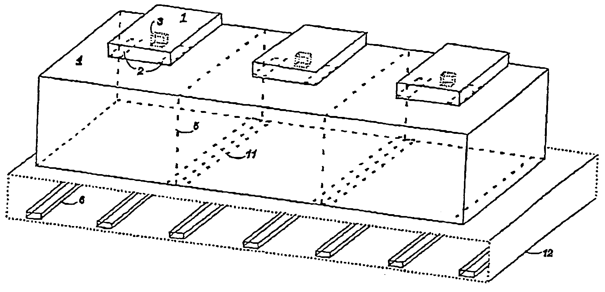
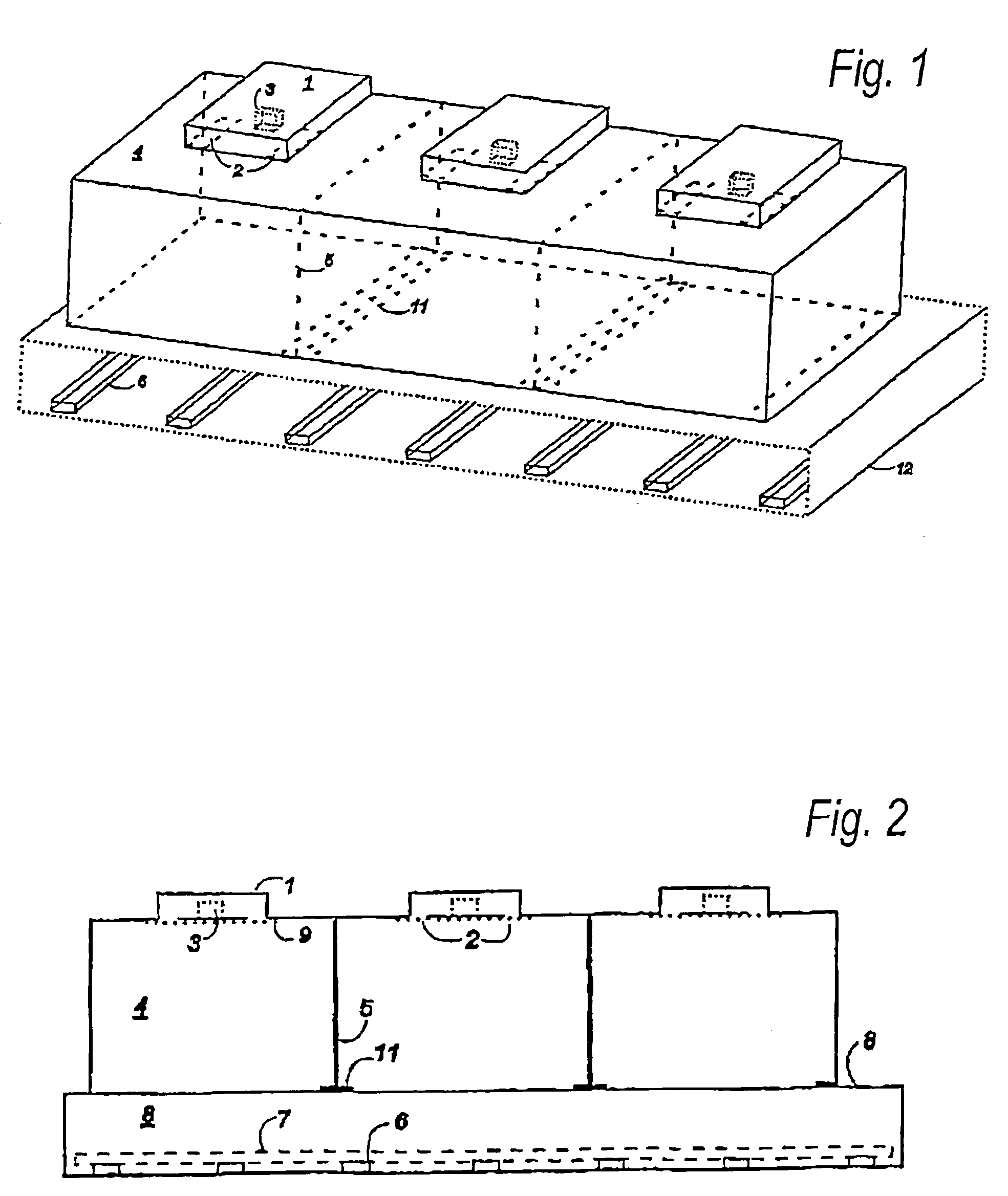
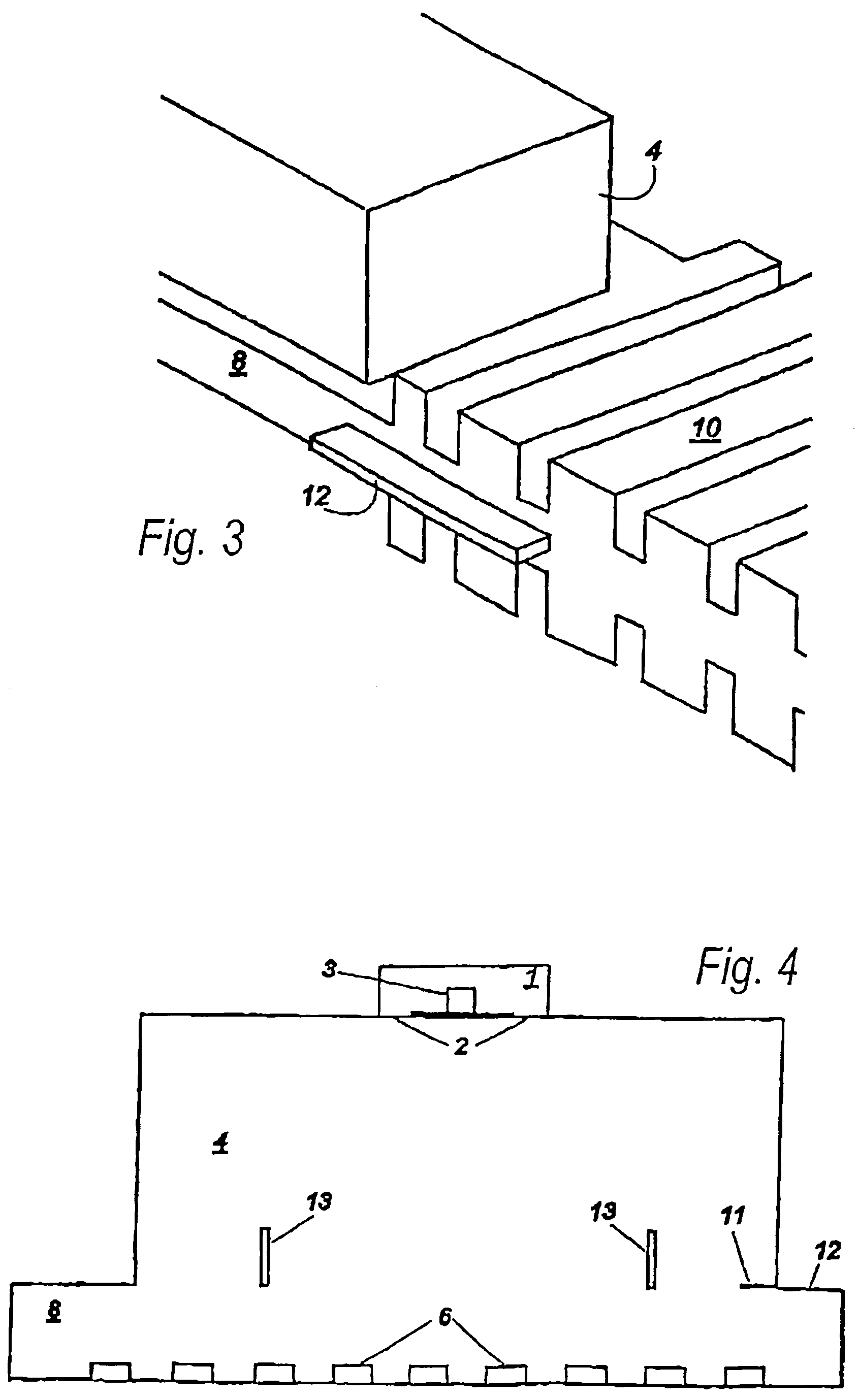
[0019]Throughout all the figures the following reference signs refer the different parts as:

[0020]1 waveguide

[0021]2 applicator feed slots (ceiling slots)

[0022]3 large metal post

[0023]4 applicator (space)

[0024]5 inter-applicator wall

[0025]6 y-directed metal bars, galvanically contacting the bottom of the tunnel r section

[0026]7 conveyor belt

[0027]8 tunnel (space)

[0028]9 applicator feed slot cover (microwave transparent)

[0029]10 mode choke in tunnel top / bottom

[0030]11 horizontal metal plates

[0031]12 tunnel side (asymmetrical)

[0032]13 horizontal metal bars for applicator mode filtering

[0033]FIG. 1 and FIG. 2 show a perspective and right view, respectively, of an applicator 4 with a conveyor belt 7. The loads are not shown. There is a low TE10 feeding waveguide 1 on top of the applicator, with two slots 2 into the applicator. There is a large metal post 3 in the region between the slots; this can be fixed to either the top or bottom plane of the waveguide. There is a vertical wall 5 be...


PUM


Abstract

A rectangular microwave applicator operating at a predetermined frequency and comprising a microwave enclosure forming a cavity having first and second transverse dimensions and a longitudinal dimension n the direction of propagation of microwave energy, wherein said dimensions are such that a main power-transferring Teym1n mode with a long vertical wavelength is enhanced, and a significant amplitude of a complementary Teym2n mode is created, wherein m1, m2 and n are positive odd integers and m2 and n are both less or equal to m1-2.

Description

FIELD OF THE INVENTION[0001]The present invention is directed to the field of open-ended microwave applicators for heating a load exterior to and not necessarily contacting the open end of the applicator. The load is typically transported on a microwave transparent conveyor and there is a metal structure below the conveyor acting both as a part of the overall microwave enclosure and for improving the heating evenness of the load.BACKGROUND OF THE INVENTION[0002]Prior art applicators of the kind within the field of this invention are described in U.S. Pat. No. 5,828,040 and EP-A2-0,746,182 (commonly referred to as PAT in the following). The particular single hybrid mode applicators of this prior art solve a major problem with still earlier prior art: that of uneven heating as evidenced by a patchy and quite unpredictable heating pattern with hot and cold spots (caused by multimode action) and that of excessive edge overheating of loads with high permittivity such as typical compact f...

Claims


Application Information

Patent Timeline
Patent Type & Authority Patents(United States)
IPC IPC(8): H05B6/70H05B6/78
CPCH05B6/6402H05B6/708H05B6/76H05B6/782
Inventor RISMAN, PER O.
Owner EXH LLC
Why Eureka
Try Eureka