Electric power steering system

a technology of electric power steering and steering wheel, which is applied in electrical steering, mechanical energy handling, transportation and packaging, etc., can solve the problems of large amount of projection in the direction of the rotation axis adversely affecting the drive controller, and increasing weight, so as to achieve excellent mountability and small amount of projection of the alternating-current motor

Inactive Publication Date: 2013-01-08
JTEKT CORP
View PDF15 Cites 9 Cited by
  • Summary
  • Abstract
  • Description
  • Claims
  • Application Information

AI Technical Summary

Benefits of technology

[0007]An object of the invention is to provide an electric power steering system in which the amount of projection of an alternating-current motor is small and that is excellent in mountability.
[0009]According to the above aspect, the control case that houses the motor drive control circuit is provided so as to overlap the control case fixation surface formed at an end portion of the mechanism housing in an axial direction of the rotary shaft, so that it is possible to reduce the projection of the alternating-current motor in the direction of the rotation axis thereof as compared to the conventional one.

Problems solved by technology

In such an electric power steering system, the weight increases due to the weight of the cable and the cable in some cases picks up noise and adversely affects the drive controller.
In the above-described electric power steering system, however, because a stator and a drive controller are coaxially arranged on the same axis as the rotation axis of the alternating-current motor, the amount of projection in the direction of the rotation axis of the alternating-current motor is large.

Method used


Image

  • Electric power steering system
  • Electric power steering system
  • Electric power steering system

Examples


Embodiment Construction

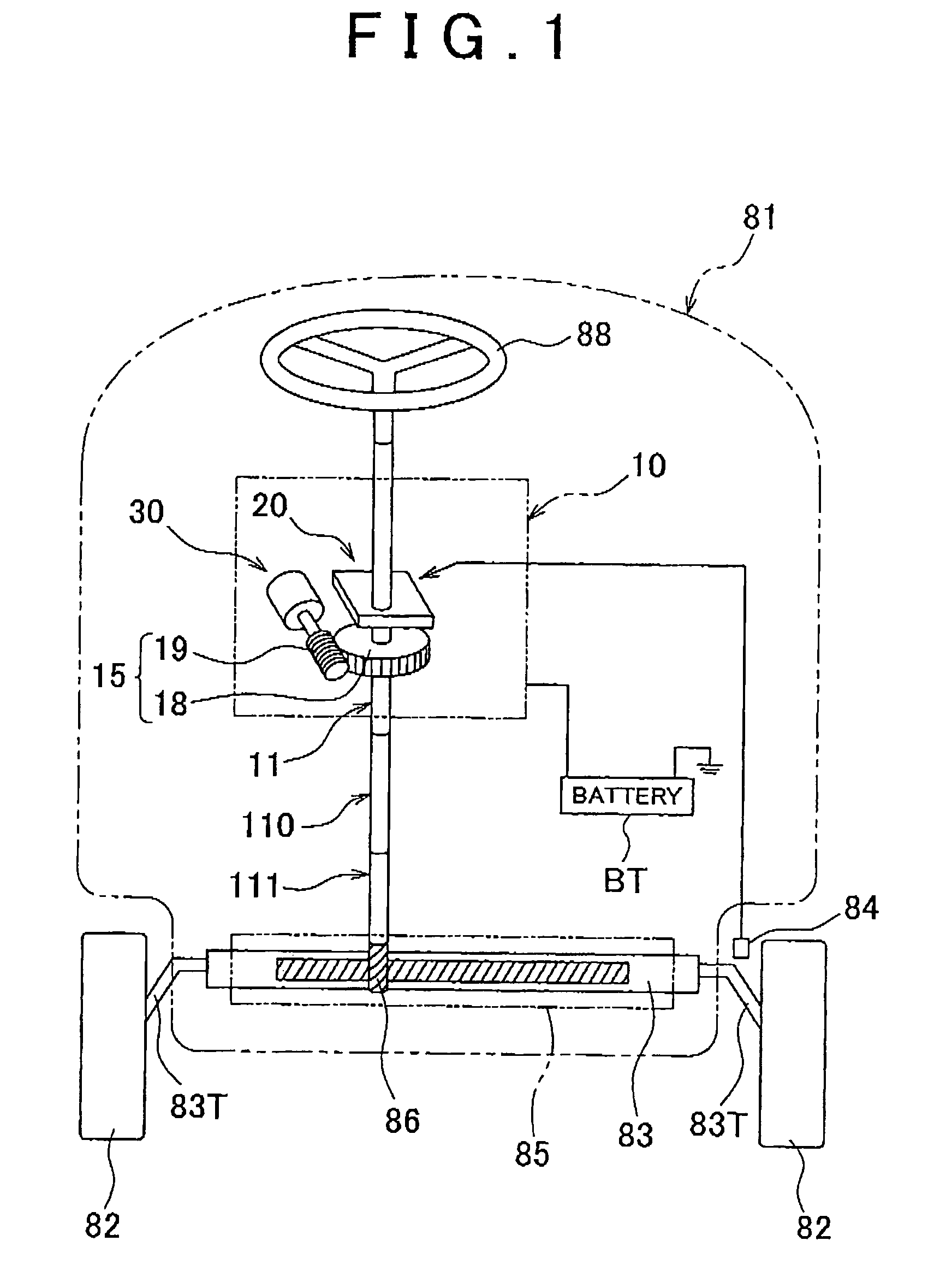
[0022]An embodiment of the invention will be described below with reference to FIGS. 1 to 11. FIG. 1 shows a vehicle 81, on which an electric power steering system 10 is mounted. A rack 83 is placed between a pair of steered wheels 82 of the vehicle 81 and is inserted into a cylindrical rack case 85. Each end of the rack 83 is connected to the steered wheel 82 through a tie rod 83T. The rack case 83 is fixed to a body of the vehicle 81. A vehicle speed sensor 84 for detecting a vehicle speed based on the rotation of the steered wheel 82 is provided near the steered wheel 82.

[0023]A pinion 86 laterally passing through a middle portion of a rack case 85 meshes with the rack 83. Between the pinion 86 and a steering wheel 88, a plurality of steering shafts 11, 110, and 111 are aligned and connected one after another via universal joints (not shown). The steering shafts 11, 110, and 111 transmit the rotation of the steering wheel 88 to the pinion 86.

[0024]As shown in FIG. 1, the electric...


PUM


Abstract

In an electric power steering system, a motor drive controller that has an inverter circuit board and a control circuit board housed in a control case is provided so as to overlap a control case fixation surface formed at an end portion of a gear housing in the axial direction of a steering shaft, so that it is possible to reduce the projection in the axial direction of a motor as compared to the conventional one. In addition, a metallic board is used for the inverter circuit board and the inverter circuit board is fixed to the control case fixation surface so as to be in surface contact therewith, so that it is possible to efficiently dissipate the heat generated on the inverter circuit board into the gear housing and a fixation support plate.

Description

INCORPORATION BY REFERENCE[0001]The disclosure of Japanese Patent Application No. 2008-274593 filed on Oct. 24, 2008 including the specification, drawings and abstract is incorporated herein by reference in its entirety.BACKGROUND OF THE INVENTION[0002]1. Field of the Invention[0003]The invention relates to an electric power steering system.[0004]2. Description of the Related Art[0005]In an electric power steering system, a drive controller that controls drive of an alternating-current motor is disposed at a position distant from the alternating-current motor, such as in a cabin of a vehicle, and the alternating-current motor and the drive controller are connected to each other by a cable. In such an electric power steering system, the weight increases due to the weight of the cable and the cable in some cases picks up noise and adversely affects the drive controller. In order to solve these problems, an electric power steering system has been developed in which a cable is shortened...

Claims


Application Information

Patent Timeline
Patent Type & Authority Patents(United States)
IPC IPC(8): B62D5/04
CPCB62D5/0406B62D5/0409H02K11/0073H02K7/1166H02K11/33
Inventor YAMAGUCHI, SHIGETOSHINIWA, TOMOHIRO
Owner JTEKT CORP
Why Eureka
Try Eureka