Fan assembly for refrigerator

a fan assembly and refrigerator technology, applied in the field of refrigerators, can solve the problems of difficult coupling or decoupling of the fan assembly through the fasteners, troublesome installation or maintenance work of the related art fan assembly, etc., and achieve the effect of preventing lead wire damage and easy mounting or disassembly

Inactive Publication Date: 2007-06-19
LG ELECTRONICS INC
View PDF4 Cites 0 Cited by
  • Summary
  • Abstract
  • Description
  • Claims
  • Application Information

AI Technical Summary

Benefits of technology

[0034]The fan assembly for the refrigerator according to the present invention so configured has advantages in that the fan assembly can be easily mounted or detached, its mounting state can be firmly maintained, and the damage of the lead wire can be prevented.

Problems solved by technology

However, the related art fan assembly has the following problems.
The installation or maintenance works for the related art fan assembly 59 are very troublesome, because there is no additional configuration for temporarily fixing the fan assembly 59.
Thus, coupling or decoupling of the fan assembly through the fasteners becomes more difficult.
Accordingly, there is a problem in that air streams are not correctly produced by the fan assembly 59 and thus air leakage can occur.
Therefore, if the lead wire comes into contact with the cooling fins of the evaporator 58, an electric leakage may occur due to the damage of insulating coating of the lead wire.
Further, since a temperature of the lead wire is lowered by the evaporator 58, there is another problem in that a withstanding voltage of the lead wire may be reduced.

Method used


Image

  • Fan assembly for refrigerator
  • Fan assembly for refrigerator
  • Fan assembly for refrigerator

Examples


Embodiment Construction

[0043]Hereinafter, a preferred embodiment of a fan assembly for a refrigerator according to the present invention will be described in detail with reference to the accompanying drawings.

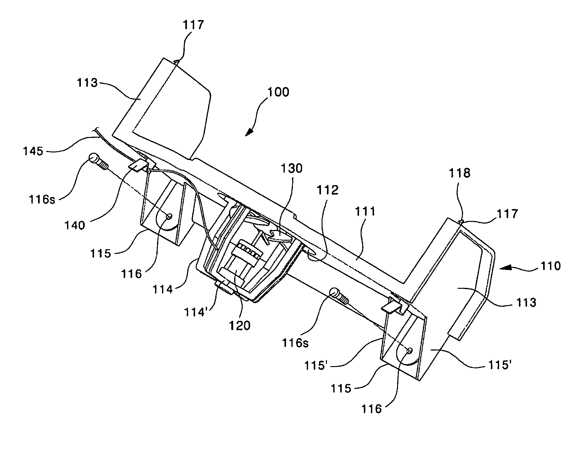
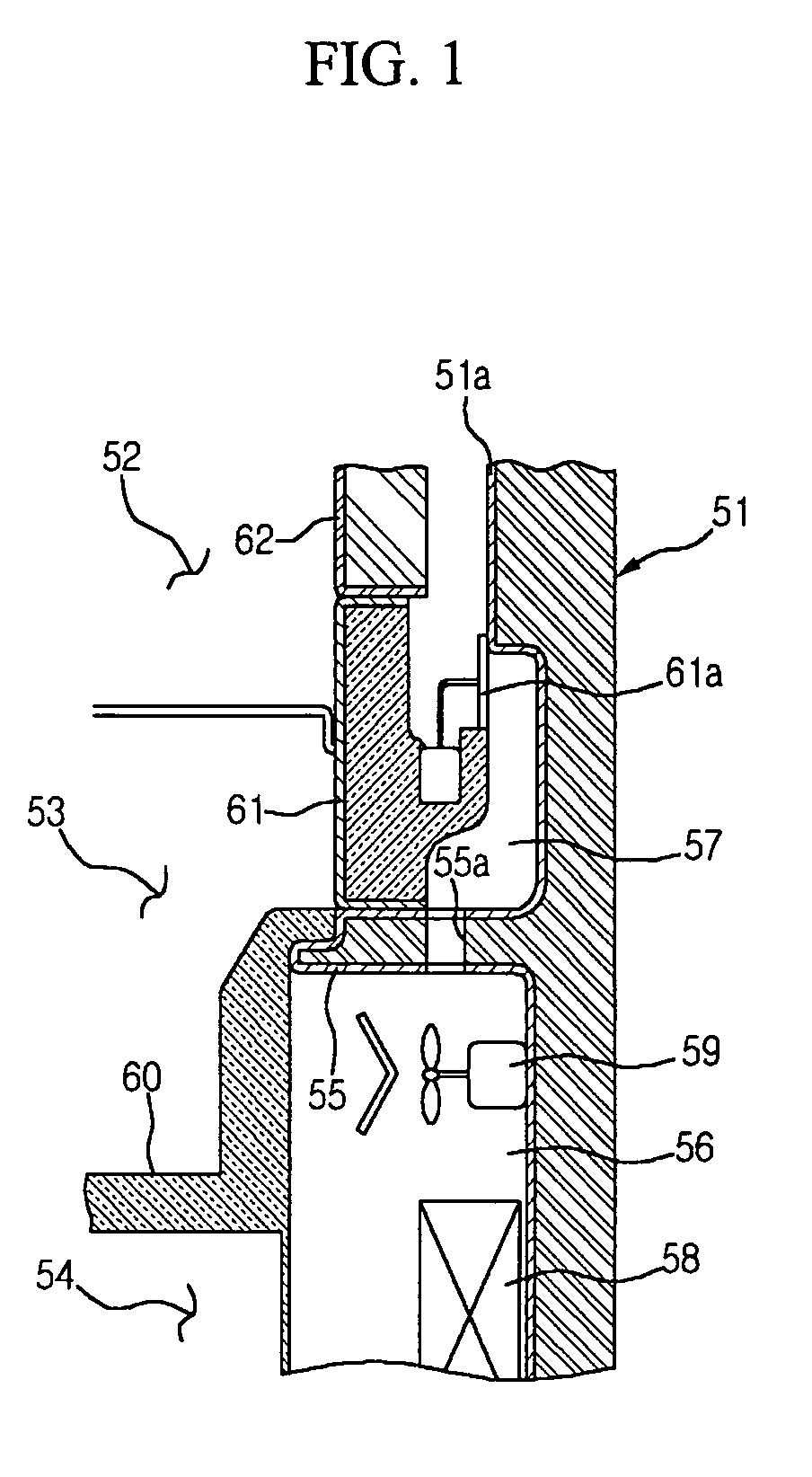
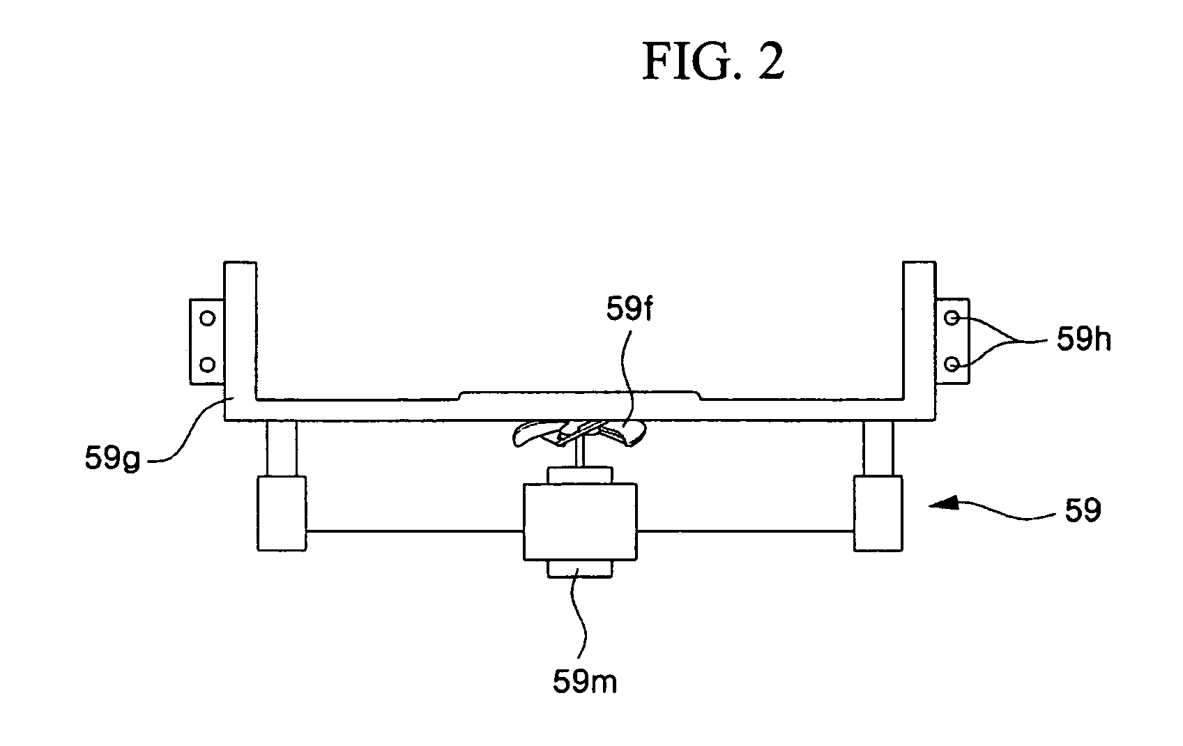
[0044]FIG. 3 is a perspective view showing the fan assembly for the refrigerator according to the preferred embodiment of the present invention; FIGS. 4a and 4b are side and plan views showing the configuration of the fan assembly according to the preferred embodiment of the present invention, respectively; and FIG. 5 is a sectional view showing a state where the fan assembly of the present invention is installed in a heat exchange chamber.

[0045]Referring to these figures, a fan assembly 100 generally comprises a fan guide 110, a fan motor 120 and a blow fan 130. The fan assembly 100 is installed in a heat exchange chamber 158 and serves to transfer cold air into a storage space of the refrigerator. In particular, the fan assembly 100 of the present invention causes the cold air to be transferred in ...


PUM


Abstract

The present invention relates to a fan assembly for a refrigerator. The fan assembly of the present invention is used in a refrigerator which includes a refrigerating chamber formed at a relatively lower portion of a main body of the refrigerator, a freezing chamber formed at a relatively upper portion of the main body and a heat exchange chamber partitioned behind at least the freezing chamber for producing cold air. The fan assembly comprises a fan motor, a blow fan driven by the fan motor for producing a cold air flow supplied to the refrigerating and freezing chambers, a fan guide through which the cold air flow passes and on which the fan motor and the blow fan are installed, at least two mounting leg which are formed on one side of the fan guide and coupled to a rear wall of the heat exchange chamber with fastening screws, a fixing hook which is formed on the fan guide at a side opposite to the mounting leg and hooked into a ceiling of the heat exchange chamber, and at least one wire hanger which is provided on the fan guide and on which a lead wire through which electrical signals for driving the fan motor are transferred is hung and supported. According to the present invention, there are advantages in that the fan assembly can be easily mounted or detached, its mounting state can be firmly maintained, and the damage of the lead wire can be prevented.

Description

[0001]This Nonprovisional application claims priority under 35 U.S.C. § 119(a) on patent application Ser. No. 10-2003-0024029 and 10-2003-0025556 filed in KOREA on Apr. 16, 2003 and Apr. 22, 2003, the entire contents of which are hereby incorporated by reference.BACKGROUND OF THE INVENTION[0002]1. Field of the Invention[0003]The present invention relates to a refrigerator, and more particularly, to a fan assembly for transferring cold air produced in a heat exchange chamber to a storage space in a refrigerator.[0004]2. Description of the Prior Art[0005]FIG. 1 shows main components of a general refrigerator. As shown in this figure, a refrigerating chamber 52, a vegetable box 53 and a freezing chamber 54 are defined sequentially from above in a main body 51 of the refrigerator. On a rear wall of the main body 51 of the refrigerator is formed a projection wall 55 protruding forwardly at a middle height of the vegetable box 53. A heat exchange chamber 56 in which cold air is produced i...

Claims


Application Information

Patent Timeline
Patent Type & Authority Patents(United States)
IPC IPC(8): F25D25/00F04D29/60F25D17/06F25D23/00
CPCF04D29/601F25D17/062F25D23/00F25D2317/067F25D2317/0681
Inventor KOO, MIN-BON
Owner LG ELECTRONICS INC
Why Eureka
Try Eureka