Ball throwing and pitching machine feeder device

a technology of a feeder device and a ball throwing machine, which is applied in the field of pitching machines, can solve the problem that the device does not give the ball to the receiver the realistic sense of batting

Active Publication Date: 2007-06-19
WILSON ORVILLE
View PDF7 Cites 22 Cited by
  • Summary
  • Abstract
  • Description
  • Claims
  • Application Information

AI Technical Summary

Benefits of technology

[0007]A ball pitching apparatus, including a propelling mechanism for propelling a ball from a first entry point to a first exit point away from the pitching apparatus in a first direction. The apparatus having a ball track for introducing the ball to the first entry point of the propelling mechanism. The ball track has a second entry point dimensioned to receive the ball and a second exit point for the introduction of the ball to the propelling mechanism, wherein the ball track is dimensioned in a generally circular or semicircular shape and constructed such that at least a portion of the ball is visible throughout the length of the path from said second entry point to said second exit point. A frame support mechanism for supporting the propelling mechanism and the ball track and for aligning the second exit point with said first entry point. Wherein a receiver positioned at said first direction in a confronting relationship to the apparatus is able to see said portion as it is conveyed along the ball track, thereby enabling the receiver to anticipate a pitching of the ball in a manner similar to an anticipation that occurs with a live ball pitcher during a windup and release of a pitch.

Problems solved by technology

These devices do not give the receiver of the ball the realistic sense of batting or catching a ball thrown by a human.

Method used


Image

  • Ball throwing and pitching machine feeder device
  • Ball throwing and pitching machine feeder device
  • Ball throwing and pitching machine feeder device

Examples


Embodiment Construction

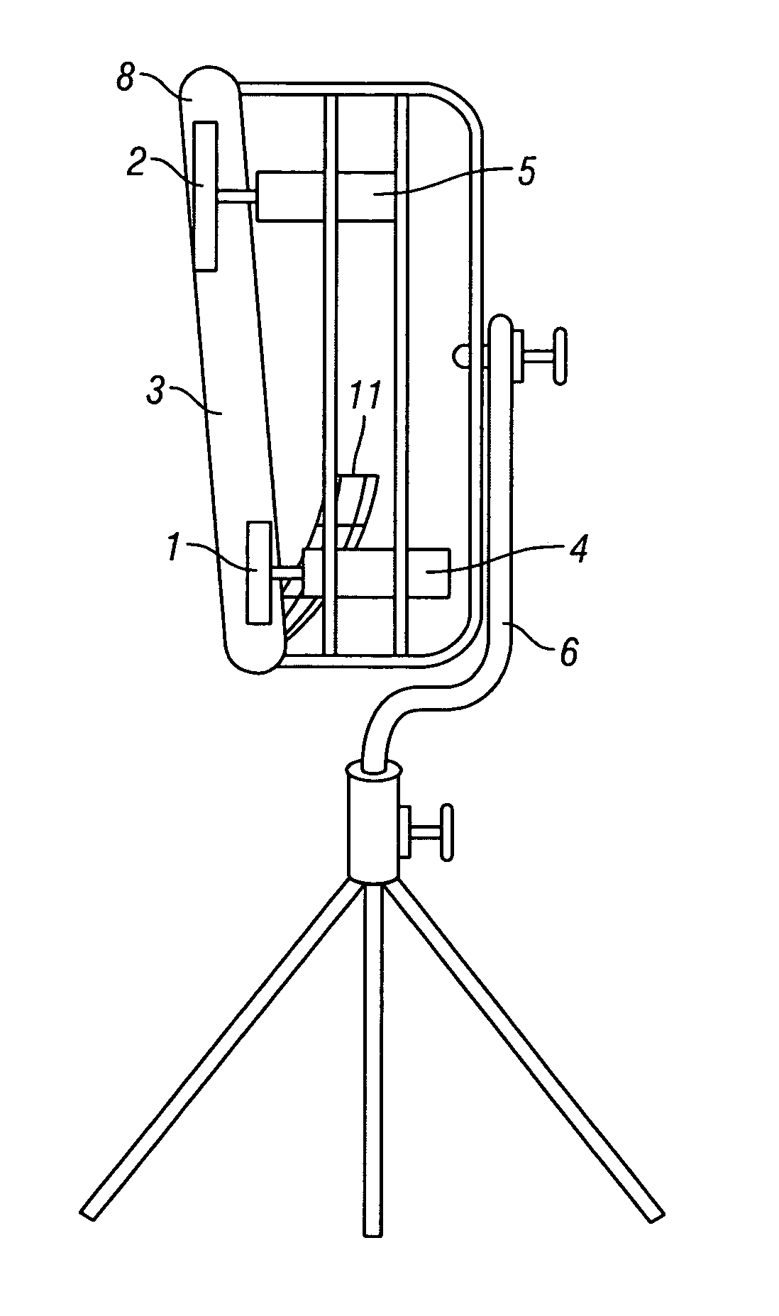
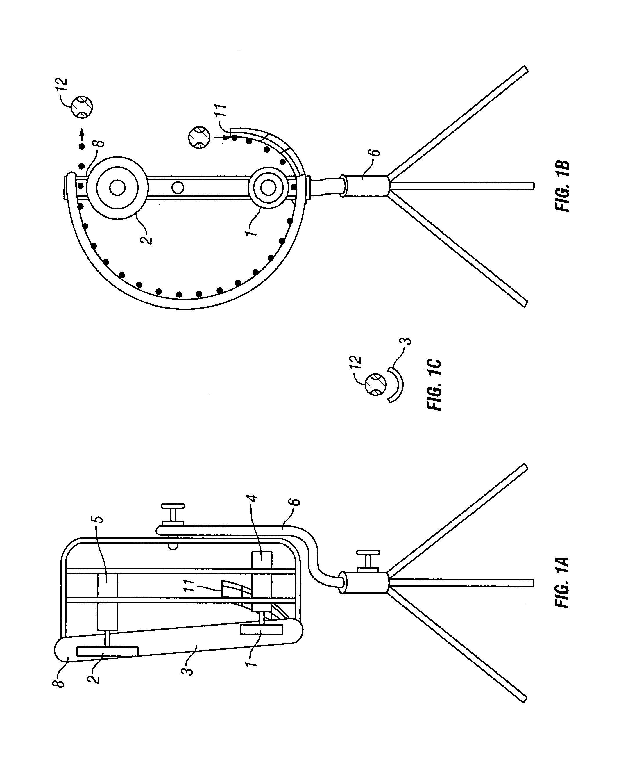
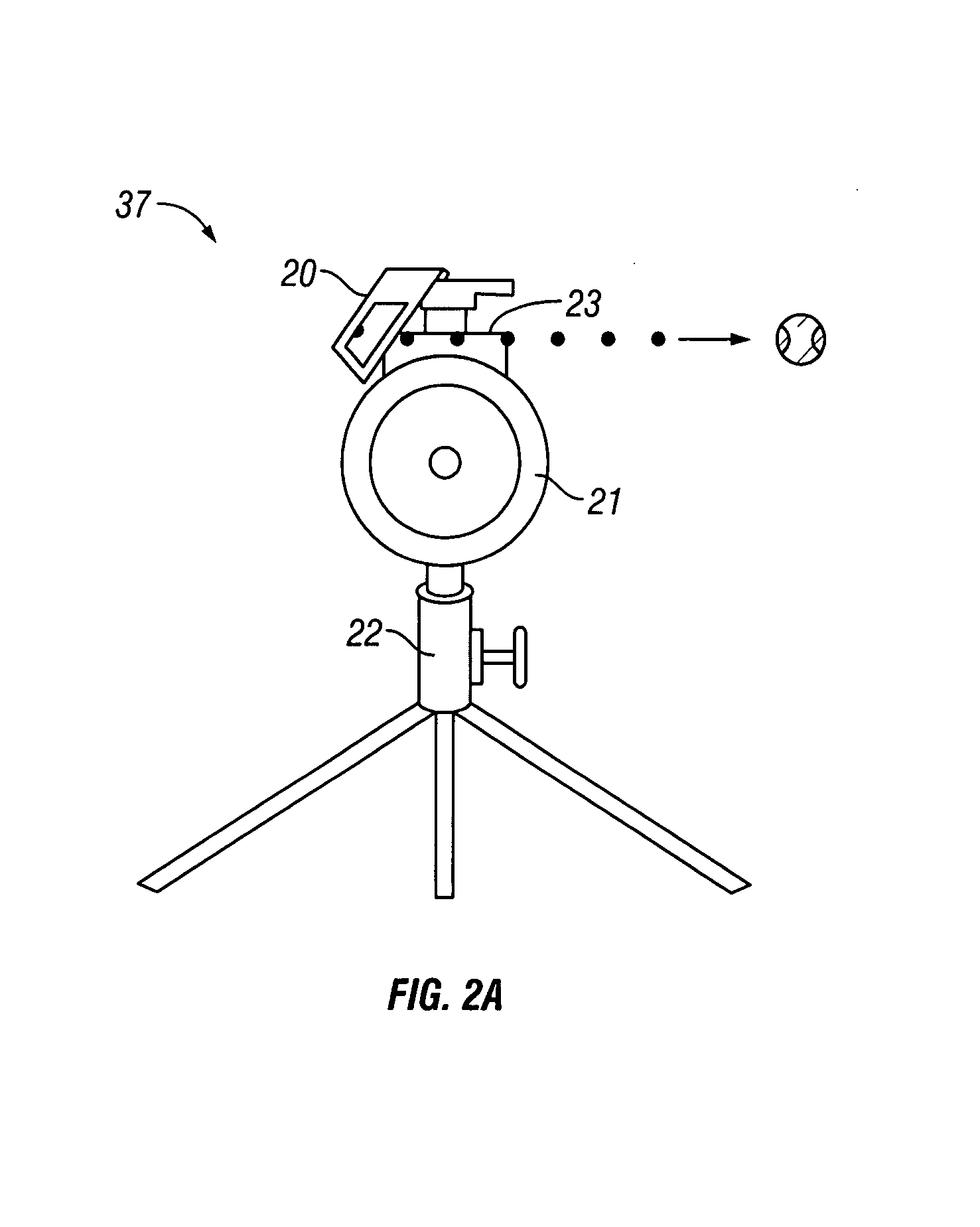
[0017]The embodiments of the invention disclosed use one or more sources to exert force or successive forces on a ball traveling through a track to rapidly propel it through the track to approximate and simulate the movement of a ball and the throwing motion of a human immediately prior to release of the ball. The invention solves the important problem of providing a more realistic environment for batting practice or catching practice for the batter or catcher to see the ball accelerate, as would be the case if the ball were thrown by a human. Seeing the motion and path of the ball, as simulated, provides a visual warning and timing mechanism prior to the ball being released. The invention may be used to throw or pitch a ball directly to a receiver and it also may be used to feed a ball into another device or pitching machine that in turn pitches the ball to the receiver.

[0018]Pitchers throw baseballs or softballs by stepping toward the target and propelling the ball with a circular...


PUM


Abstract

A ball pitching device that, prior to release and delivery of the ball to a receiver, propels the ball through a circular loop or semi-circular arc in a manner that is visible to the receiver to simulate the path of a person's hand in the act of throwing. The invention enable a more realistic simulation of an overhand or side arm throwing motion as are commonly used for pitching baseballs and to also simulate the underhand throwing motion used in softball.

Description

CROSS-REFERENCE TO RELATED APPLICATIONS[0001]This application claims the benefit of U.S. Provisional Application No. 60 / 589,278, filed Jul. 20, 2004, entitled “Ball Throwing and Pitching machine Feeder Device”.STATEMENT REGARDING FEDERALLY SPONSORED RESEARCH OR DEVELOPMENT[0002]This invention does not include any federally sponsored research or development.BACKGROUND OF THE INVENTION[0003]This invention relates to a pitching machine and, more particularly, to a ball pitching machine for pitching a baseball or softball or any other type of ball. Various forms of ball pitching machines are known in the prior art which are said to simulate the speed and trajectory of balls as if pitched by an actual person.[0004]There is known in the prior art devices to throw or pitch baseballs and / or softballs to a receiver such as a batter or catcher. These devices include machines to hurl a ball using a mechanical arm or lever. The arm is rotated and the ball is thrown from one end of the arm. Othe...

Claims


Application Information

Patent Timeline
Patent Type & Authority Patents(United States)
IPC IPC(8): F41B4/00
CPCA63B69/406
Inventor WILSON, ORVILLE
Owner WILSON ORVILLE
Why Eureka
Try Eureka