Renewable energy flashlight

a flashlight and renewable energy technology, applied in the field of renewable energy flashlights, can solve the problems of loss of rebound energy, rapid wear of parts, and fatigue of springs, and achieve the effects of reducing waste in human exertion, increasing the rebounding speed of the charging magnet, and improving recharging efficiency

Inactive Publication Date: 2007-06-19
RSGA
View PDF14 Cites 20 Cited by
  • Summary
  • Abstract
  • Description
  • Claims
  • Application Information

AI Technical Summary

Benefits of technology

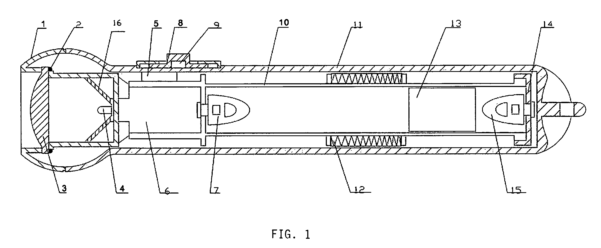
[0015]A pair of elastomagnetic rebound members is then opposedly mounted with one at each of the two ends of the transverse chamber. Each rebound member is comprised of an elastic rebounding material such as rubber or silicone into which is reflexively seeded at least one internal magnet. These rebound members are opposedly mounted in polar opposition to the charging magnet to elastically and magnetically assist in rebounding there between the charging magnet. Each of the elastomagnetic repulsion members is void of any moving parts. They employ natural reverse polarity to reduce waste in human exertion required to shake the charging magnet to power the light emitting diode. All that is needed is a simple horizontal rolling motion of the wrist. Because of the increase in the rebounding speed of the charging magnet, recharging efficiency is increased by as much as 70% thereby reducing charge time. These rebound members simultaneously eliminate the vibration stress damage on electronic components and allow the charging magnet to pass completely through the copper coil for a complete inductive cycle. As they do not employ conventional springs, they are lighter and easier to handle and not subject to spring fatigue.
[0016]This design facilitates the manual horizontal movement of the flashlight so that the magnet slides through the copper coil, and creates a natural enhanced repulsion at each end of the transfer tube to take advantage of the momentum of the magnet upon passing through the copper coil and propel its return trip to the opposite end of the transfer tube. Light emitting diode power consumption is less than that generated by gentle shaking with minimal wrist energy. The result is an efficient sealed mechanical system, which can be continuously operated with minimal human energy expense and maximum device power generation and management.
[0024]The renewable energy flashlight preferably includes a concave reflective mirror surrounding the light emitting diode structured to capture and direct light through the lens to enhance the light beam. This reduces significantly the lost light through the head of the housing.

Problems solved by technology

These Vetorino '719 repeated magnet-to-magnet contacts jar the reciprocating components of the renewable energy flashlight and result in loss of rebound energy and rapid wear of the parts.
The Vetorino '719 springs suffer from spring fatigue over time, or spring deformation if shaken too hard.
The Mah '714 dual spring bumpers also suffer from spring deformation and declining rebound performance caused by spring fatigue.
This spring fatigue in the Mah '714 dual spring bumpers can occur very rapidly.
If shaken too hard, the spring(s) become misshapen causing the rubber bumper to rub against the side of the internal tube or not return the charging magnet in a directly lateral direction.
When this happens, the affected bumper is rendered virtually useless.
This lack of reflexive properties causes a heavy thump at each end of the tube, when shaken.
As such, it suffers from all of the Mah '714 spring fatigue and spring distortion charging problems.

Method used


Image

  • Renewable energy flashlight
  • Renewable energy flashlight
  • Renewable energy flashlight

Examples


Embodiment Construction

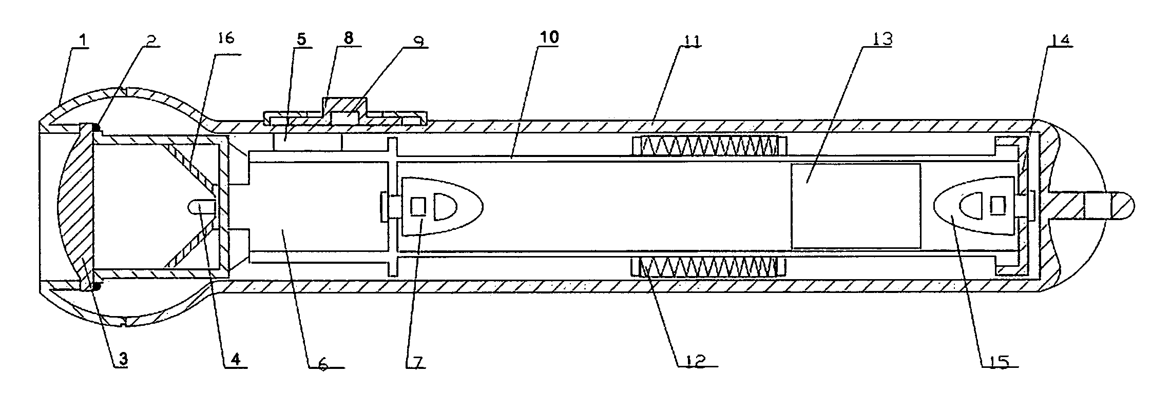
[0034]One preferred embodiment of the renewable energy flashlight is shown in the FIG. 1 side cross section. The components shown are as follows:[0035]1. Bezel[0036]2. Seal[0037]3. Beam magnifying lens[0038]4. Light Emitting Diode (LED)[0039]5. Sealed ferrous reed switch[0040]6. Circuit board with capacitor[0041]7. Seed Magnet[0042]8. Sliding plastic switch shield[0043]9. Switch Magnet[0044]10. Inner tubular carriage[0045]11. Polycarbonate outer shell housing[0046]12. Copper induction coil[0047]13. Charging magnet[0048]14. Tube sealing base cap[0049]15. Elastomagnetic rebound member[0050]16. Reflecting bowl mirror

[0051]Sealed within the renewable polycarbonate outer shell housing 11 is an inner tubular carriage 10 into which is slideably mounted a charging magnet 13. The tubular carriage 10 is surrounded by a copper coil 12, such that as the charging magnet 13 reciprocates there through an electrical current is generated, which is collected on the circuit board capacitor 6.

[0052]A p...


PUM


Abstract

A renewable energy flashlight employing a pair of elastomagnetic repulsion members to assist in reciprocating a charging magnet passing through surrounding induction coils to enhance the efficiency of manually charging a capacitor to power an LED lens amplified flashlight.

Description

BACKGROUND OF THE INVENTION[0001]1. Field of Invention[0002]The present invention relates to renewable energy flashlights. In particular, it relates to a renewable energy flashlight employing a pair of elastomagnetic repulsion members to assist in reciprocating a charging magnet passing through surrounding induction coils to enhance the efficiency of manually charging a capacitor to power a light emitting diode lens amplified flashlight.[0003]2. Description of Related Art[0004]Various renewable flashlights are known. Vetorino, U.S. Pat. No. 6,220,719 discloses a renewable energy flashlight employing a reciprocating charging magnet traversing a travel chamber enwrapped with induction coils to generate a current, when manually shaken. The ends of the travel chamber have reverse polarity magnets to that of the charging magnet, which directly contact and repel the charging magnet to aid in reciprocating the charging magnet. These Vetorino '719 repeated magnet-to-magnet contacts jar the ...

Claims


Application Information

Patent Timeline
Patent Type & Authority Patents(United States)
IPC IPC(8): F21L13/06
CPCF21L13/06F21L4/027F21Y2101/02F21Y2115/10
Inventor LONG, JON DARINTIANMING, QIAN
Owner RSGA
Why Eureka
Try Eureka