Eureka AIR delivers breakthrough ideas for toughest innovation challenges, trusted by R&D personnel around the world.

Electrical connector with improved shielding means

a shielding means and electrical connector technology, applied in the direction of coupling device details, coupling device connections, printed circuits, etc., can solve the problem that the connector cannot achieve the desirable effect of preventing electromagnet interference, and achieve the effect of superior shielding characteristics

Inactive Publication Date: 2007-06-19
HON HAI PRECISION IND CO LTD
View PDF5 Cites 27 Cited by
  • Summary
  • Abstract
  • Description
  • Claims
  • Application Information

AI Technical Summary

Benefits of technology

[0006]An object of the present invention is to provide an electrical connector having superior shielding characteristics.

Problems solved by technology

However, there are a plurality of slots between adjacent strips, therefore, electromagnetic radiation of certain frequency could penetrate through the slots, the connector could not achieve desirable effect of preventing electromagnet interference.

Method used


Image

  • Electrical connector with improved shielding means
  • Electrical connector with improved shielding means
  • Electrical connector with improved shielding means

Examples


Embodiment Construction

[0020]Reference will now be made to the drawing figures to describe the preferred embodiment of the present invention in detail.

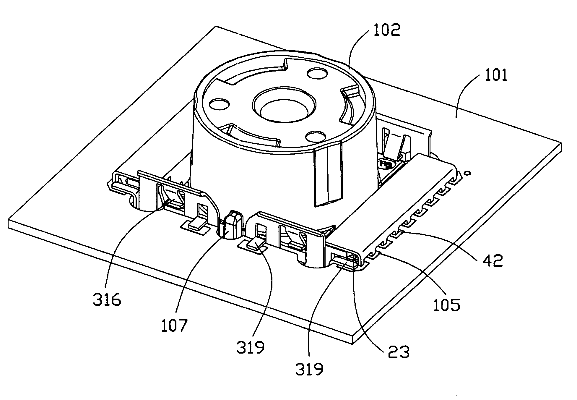
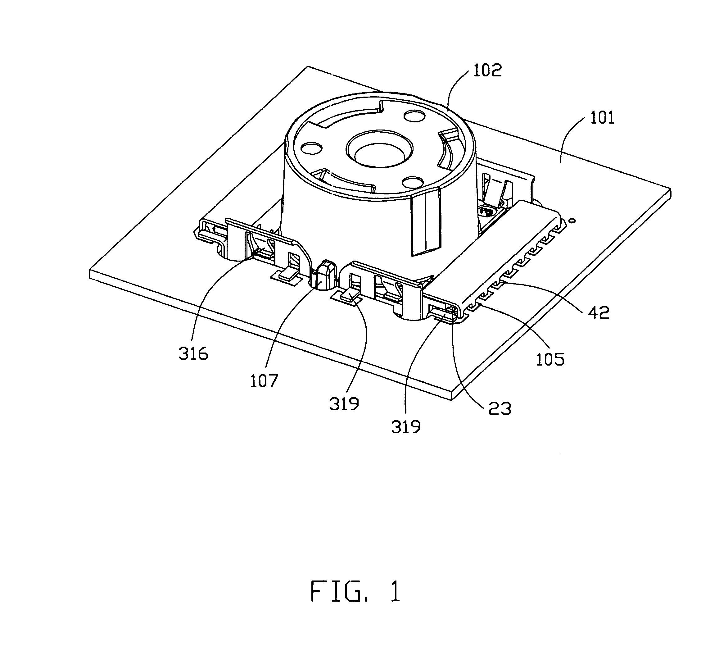
[0021]Referring to FIGS. 1, 3 and 8, an electrical connector 100 mounted on a printed circuit board 101 for receiving an electrical module such as camera module 102, comprises an insulative housing 1, a plurality of contacts 2 fixed to the housing 1, an inner shell 4 attached to the housing 1 and a substantially box-like outer shell 3 for receiving the housing 1 and the inner shell 4.

[0022]Referring to FIGS. 9, 10, the insulative housing 1 includes a vertical main portion 11 and a horizontal portion 12 extending laterally from an upper edge of the main portion 11. The main portion 11 is provided with a locking hole 111 for locking with the outer shell 3 and a retention hole 112 for engaging with the inner shell 4.

[0023]The contacts 2 are configured in a “Z”-shape, each comprises a vertical intermediate portion 21 insert molded with said housing 1, a contact...


PUM


Abstract

A shielded electrical connector (100) for receiving a module includes a shielding shell (3) mounted to a printed circuit board, an insulative housing (1) assembled to the shell and equipped with a number of contacts (2). Each contact has a contacting portion (22) for contacting with the module and a soldering portion (23) extending beyond the shell for connection to the printed circuit board. The shell comprises a bottom plate (32) extending in a direction perpendicular to the module insertion direction and a plurality of side plates (310, 311, 312, 313) extending upwardly from the bottom plate and cooperating with the bottom plate to form a receiving space for receiving the module. Every two adjacent side plates are connected to each other.

Description

BACKGROUND OF THE INVENTION[0001]1. Field of the invention[0002]The present invention generally relates to a shielded electrical connector, particularly to a shielded electrical connector for receiving an electrical element therein.[0003]2. Description of Related Art[0004]A conventional shielded electrical connector described in U.S. patent application Publication No. 2003 / 0218873 comprises a fastening structure for fastening an electrical element 3 having a plurality of projections. The fastening structure comprises a frame 1 with a plurality of flexible strips 11 arranged therearound, and an adapter 2 with a plurality of U-shaped contacts mounted on. However, there are a plurality of slots between adjacent strips, therefore, electromagnetic radiation of certain frequency could penetrate through the slots, the connector could not achieve desirable effect of preventing electromagnet interference. Furthermore, the adapter 2 together with the terminals is placed between the electrical...

Claims


Application Information

Patent Timeline
Patent Type & Authority Patents(United States)
IPC IPC(8): H01R12/00H05K1/00
CPCH01R13/65802H01R13/6582H01R13/6594
Inventor CHEN, MING-CHING
Owner HON HAI PRECISION IND CO LTD
Why Eureka
Eureka Blog
Learn More