Electrical connector using a substrate as a contacting member

a technology of contacting member and electrical connector, which is applied in the direction of coupling device connection, electrical discharge lamp, coupling device details, etc., can solve the problems of putting more severe pressure on the manufacturers of connectors, and achieve the effect of reducing crosstalk regardless of the length of the connected cabl

Inactive Publication Date: 2007-06-19
DDK LTD
View PDF13 Cites 18 Cited by
  • Summary
  • Abstract
  • Description
  • Claims
  • Application Information

AI Technical Summary

Benefits of technology

[0010]It is an object of the invention to provide an improved electrical connector which, in view of the problems of the prior art described above, achieves the miniaturization of the connector, and stabilization of impedance, and accomplishes the reduction in crosstalk regardless of length of connected cables.
[0015]As can be seen from the explanation described above, the electrical connector 10 according to the invention can bring about the following significant effects.
[0016](1) The electrical connector according to the invention comprises a housing 12, a substrate 14, and shielding plates 16, the housing having an inserting hole 30 for the substrate 14, the substrate having a plurality of signal patterns 20 and a plurality of ground patterns 22 alternately arranged on at least one surface of the substrate in a manner that one signal pattern 20 is between two ground patterns 22, the signal patterns and the ground patterns each having a contact portion 26 to contact a mating object and a connection portion 28 to be connected to a cable, and the shielding plates 16 each connected to the connection portion 28 of the ground pattern 22 for shielding. It is, therefore, possible to miniaturize the connector 10 to the fullest extent and to achieve the reduction in crosstalk regardless of lengths of cables to be connected.
[0017](2) According to the invention, a plurality of signal patterns 20 and a plurality of ground patterns 22 are alternately arranged on both the surfaces of the substrate 14 in a manner that one signal pattern 20 is between two ground patterns 22, and the shielding plates 16 of a substantially U-shape are each connected to the connection portion 28 of the ground pattern 22. With this construction, simultaneously with the miniaturization of the electrical connector 10, the shielding plates 16 can be easily connected to the connector without increasing the number of parts so that about 25% of the crosstalk can be reduced in comparison with those in the prior art, even if there are variations in frequency, height of shielding plates 16 and pitches of signal patterns 22.
[0019](4) According to the invention, the locking members 18 are substantially U-shaped. The substrate 14 can be securely fixed to the housing 12 without increasing the number of parts, thereby achieving the stable connection.

Problems solved by technology

In recent years, with the miniaturization of electric or electronic appliances, the requirement of miniaturization for electrical connector has put more severe pressure on manufacturers of connectors.

Method used


Image

  • Electrical connector using a substrate as a contacting member
  • Electrical connector using a substrate as a contacting member
  • Electrical connector using a substrate as a contacting member

Examples


Embodiment Construction

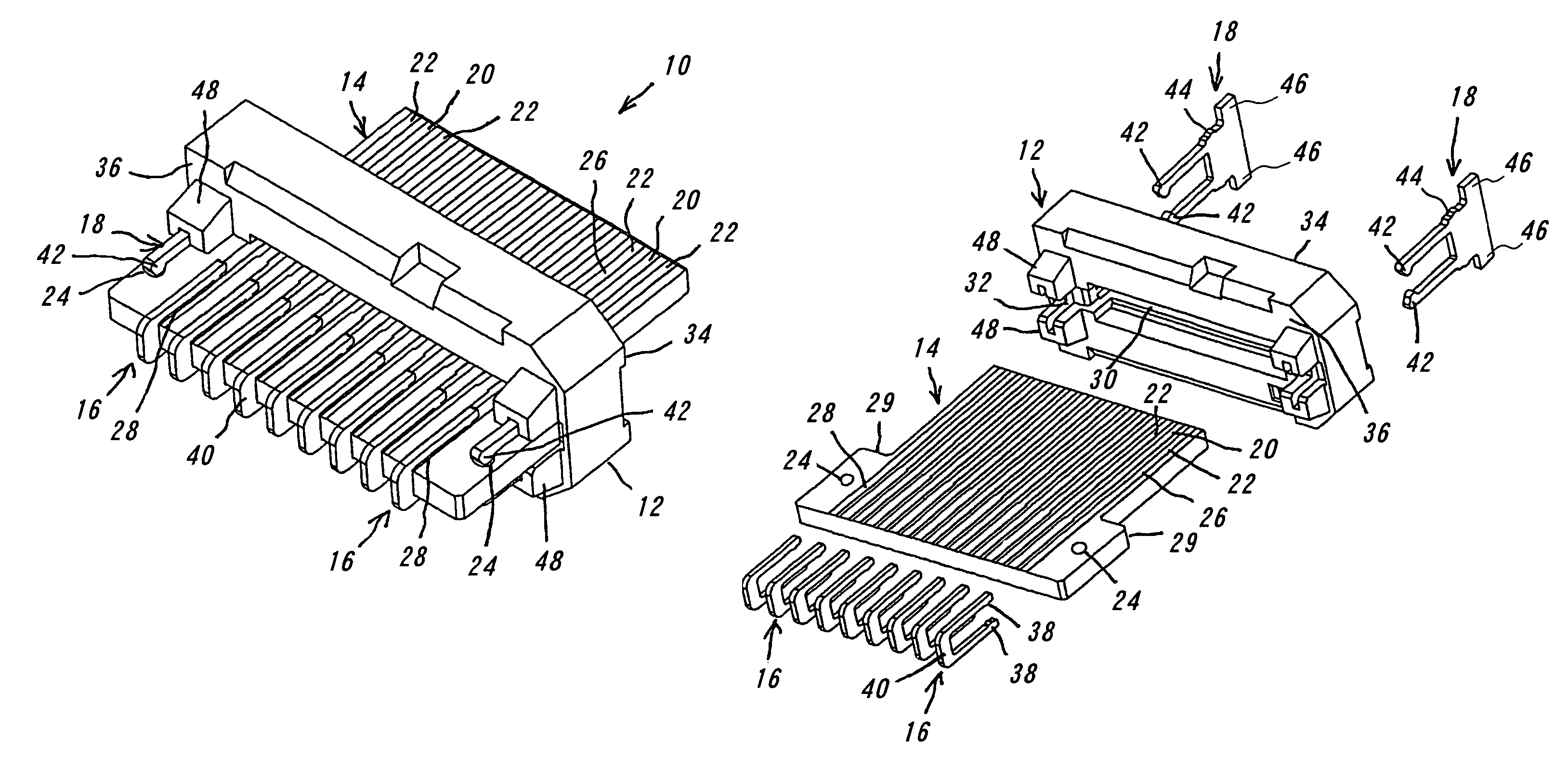
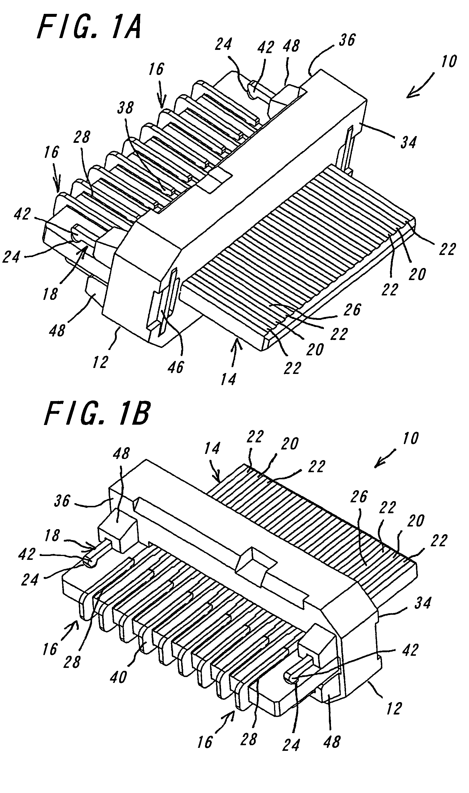
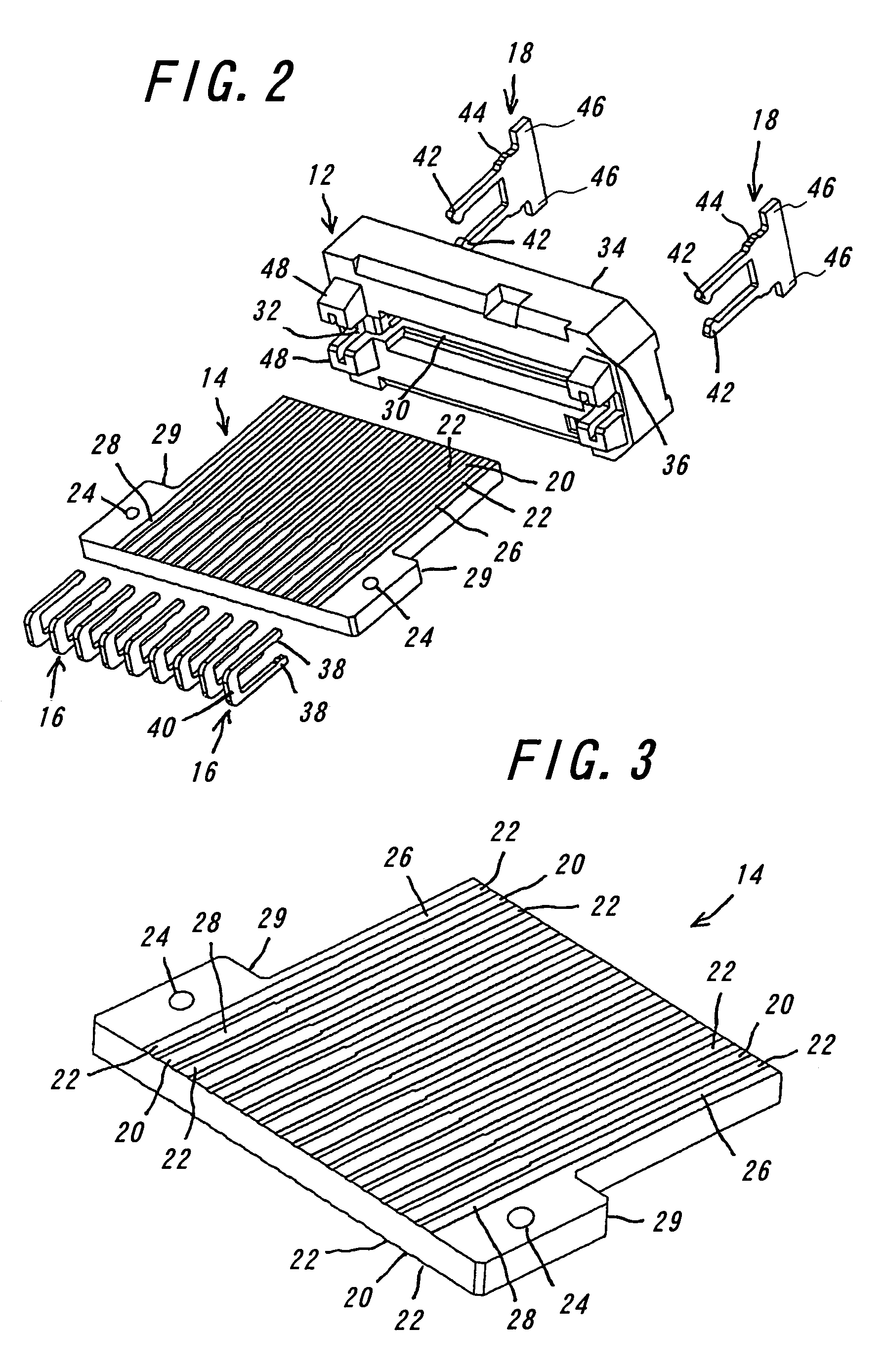
[0028]One embodiment of the electrical connector 10 according to the invention will be explained with reference to FIGS. 1 to 5 hereinafter. FIG. 1A is a perspective view of the electrical connector of the invention viewed from its fitting side, and FIG. 1B is a perspective view of the connector viewed from the connecting side. FIG. 2 is an exploded perspective view of the connector viewed from the connecting side. FIGS. 3, 4 and 5 are perspective views of the substrate, shielding plate and locking member used in the electrical connector according to the invention, respectively.

[0029]The electrical connector 10 of the one embodiment according to the invention mainly comprises a housing 12, a substrate 14, shielding plates 16 and locking members 18. In the electrical connector 10, instead of electric contacts, the substrate 14 is used as a contacting members in contact with mating objects in order to achieve a narrower pitch and hence a miniaturization of the connector 10.

[0030]First...


PUM


Abstract

An electrical connector includes a housing, a substrate, and shielding plates. The housing has an inserting hole for the substrate, and the substrate has a plurality of signal patterns and a plurality of ground patterns alternately arranged on at least one surface of the substrate in a manner that one signal pattern is between two ground patterns. The signal patterns and the ground patterns each have a contact portion to contact a mating object and a connection portion to be connected to a cable. The shielding plates are each connected to the connection portion of the ground pattern for shielding. With this construction, the electrical connector achieves its miniaturization and reduction in crosstalk regardless of length of connected cables.

Description

CROSS-REFERENCE TO RELATED APPLICATIONS[0001]This application claims priority from Japanese Patent Application No. 2004-192780, filed Jun. 30, 2004, which is incorporated by reference in its entirety.BACKGROUND OF THE INVENTION[0002]This invention relates to an electrical connector for use in electric or electronic appliances such as servers, super computers and the like, and more particularly to an improved electrical connector capable of minimizing crosstalk when being connected to cables.[0003]In recent years, with the miniaturization of electric or electronic appliances, the requirement of miniaturization for electrical connector has put more severe pressure on manufacturers of connectors. In many cases, generally, an electrical connector comprises insulators formed of electrically insulating materials and electric contacts formed of a conductive material. The electric contacts each comprise a contact portion to contact a mating object, a fixed portion to be fixed to the insulat...

Claims


Application Information

Patent Timeline
Patent Type & Authority Patents(United States)
IPC IPC(8): H01R24/00
CPCH01R13/65807H01R13/6585H01R13/6471H01R13/6474H01R13/6658H01R2201/06
Inventor ISHIZUKA, SHINYAOZAI, KAZUYUKI
Owner DDK LTD
Why Eureka
Try Eureka