Injection compression molding apparatus and injection compression molding method

a technology of injection compression molding and injection compression molding, which is applied in the field of injection compression molding apparatus, injection compression molding die, injection, etc., can solve the problems of poor energy efficiency, complex die construction, and high cost of die manufacture, so as to reduce injection pressure loss, and simplify the die construction

Inactive Publication Date: 2006-04-04
MEIKI
View PDF3 Cites 12 Cited by
  • Summary
  • Abstract
  • Description
  • Claims
  • Application Information

AI Technical Summary

Benefits of technology

[0012]In view of the above problems, it is an object of the present invention to simplify the construction of dies and prevent loss of resin and heat due to solidification of the resin in a pa

Problems solved by technology

However, in the injection compression apparatus described above, as the resin path, the reservoir and the like are formed between the resin injection hole provided on the bottom surface of the lower die and the cavity, there are problems in that:(1) the construction of the dies is complicated and it is costly to manufacture the dies;(2) since the resin is solidified in said path, reservoir and the like at the time of molding, loss of the resin as well as

Method used


Image

  • Injection compression molding apparatus and injection compression molding method
  • Injection compression molding apparatus and injection compression molding method
  • Injection compression molding apparatus and injection compression molding method

Examples


Embodiment Construction

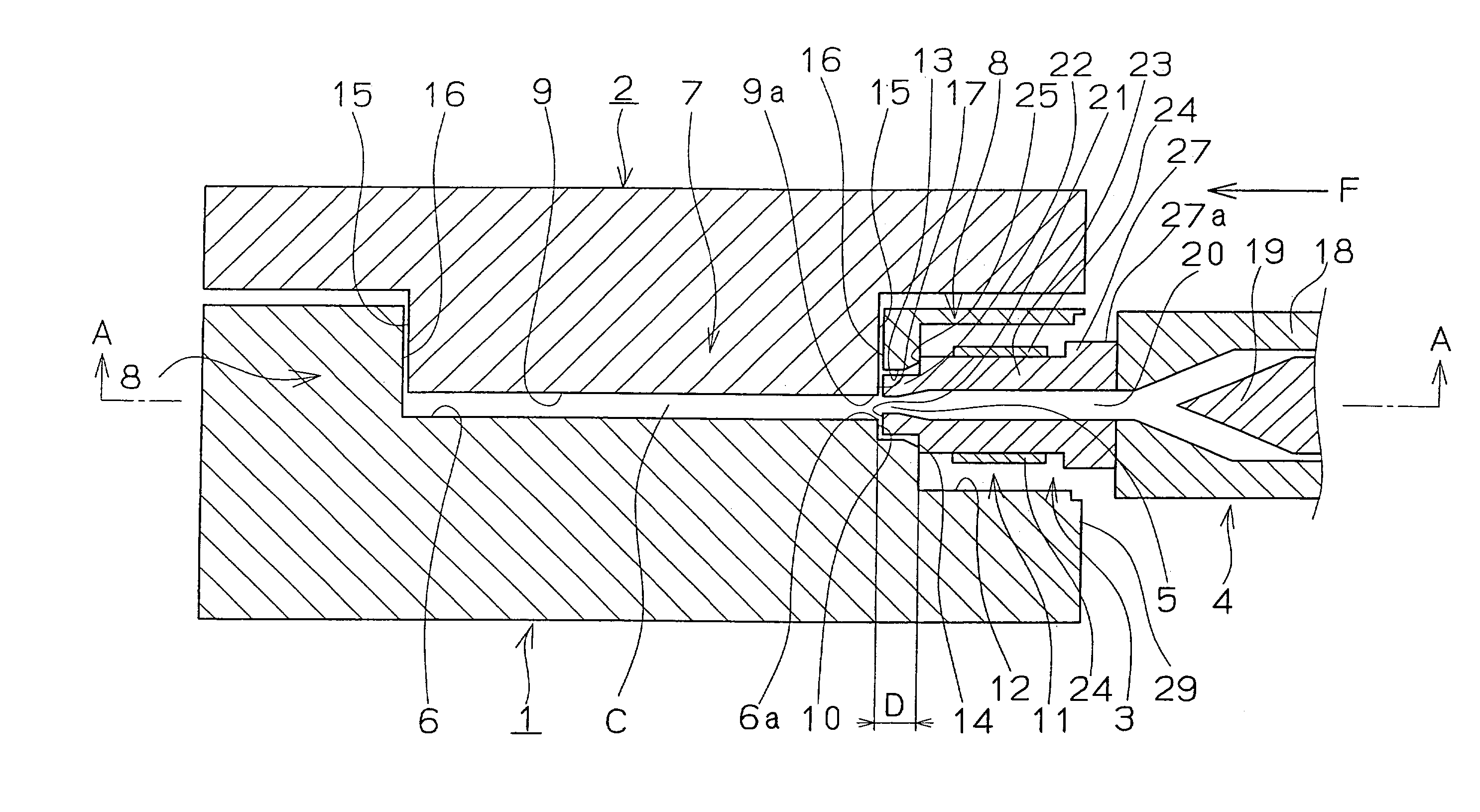
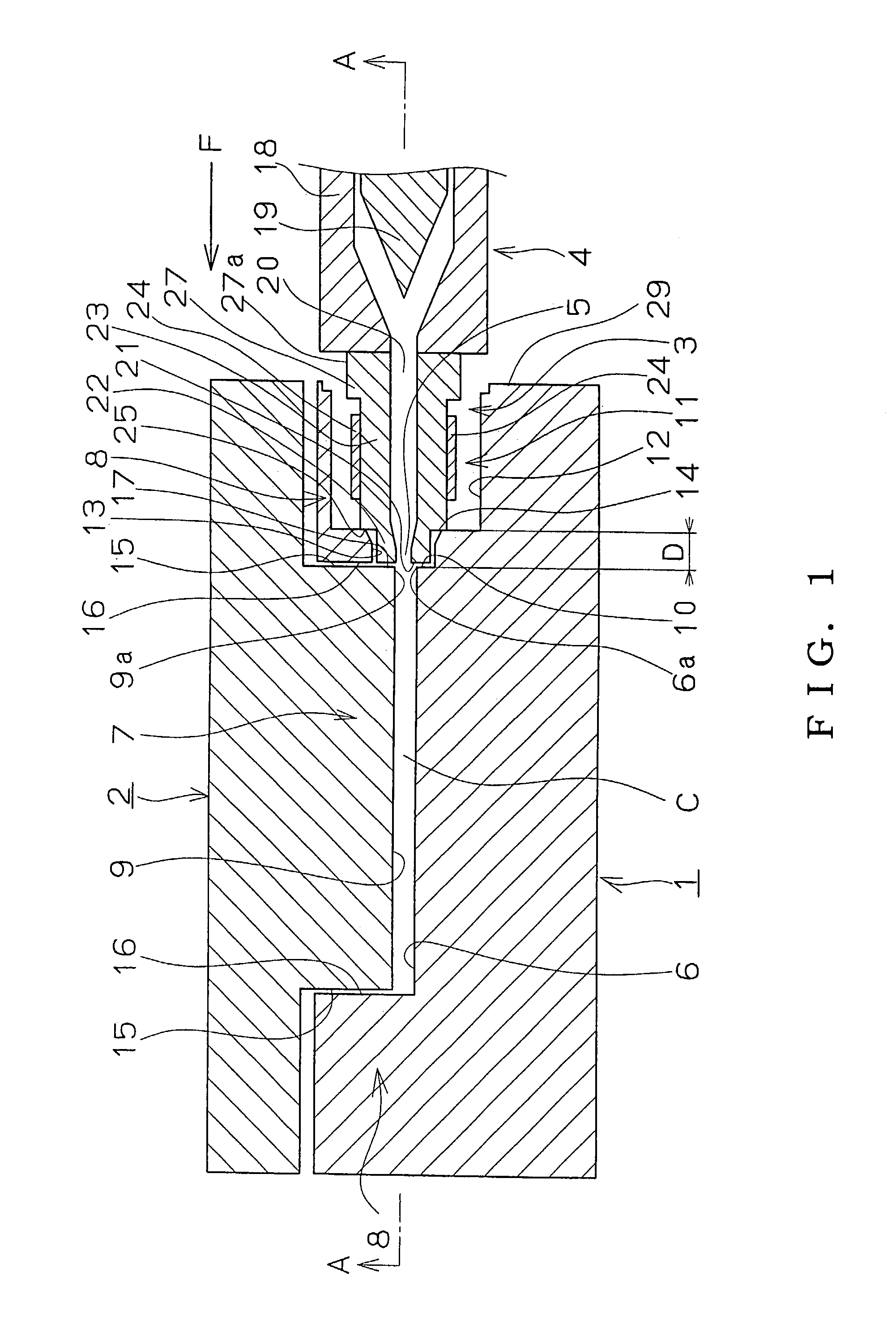
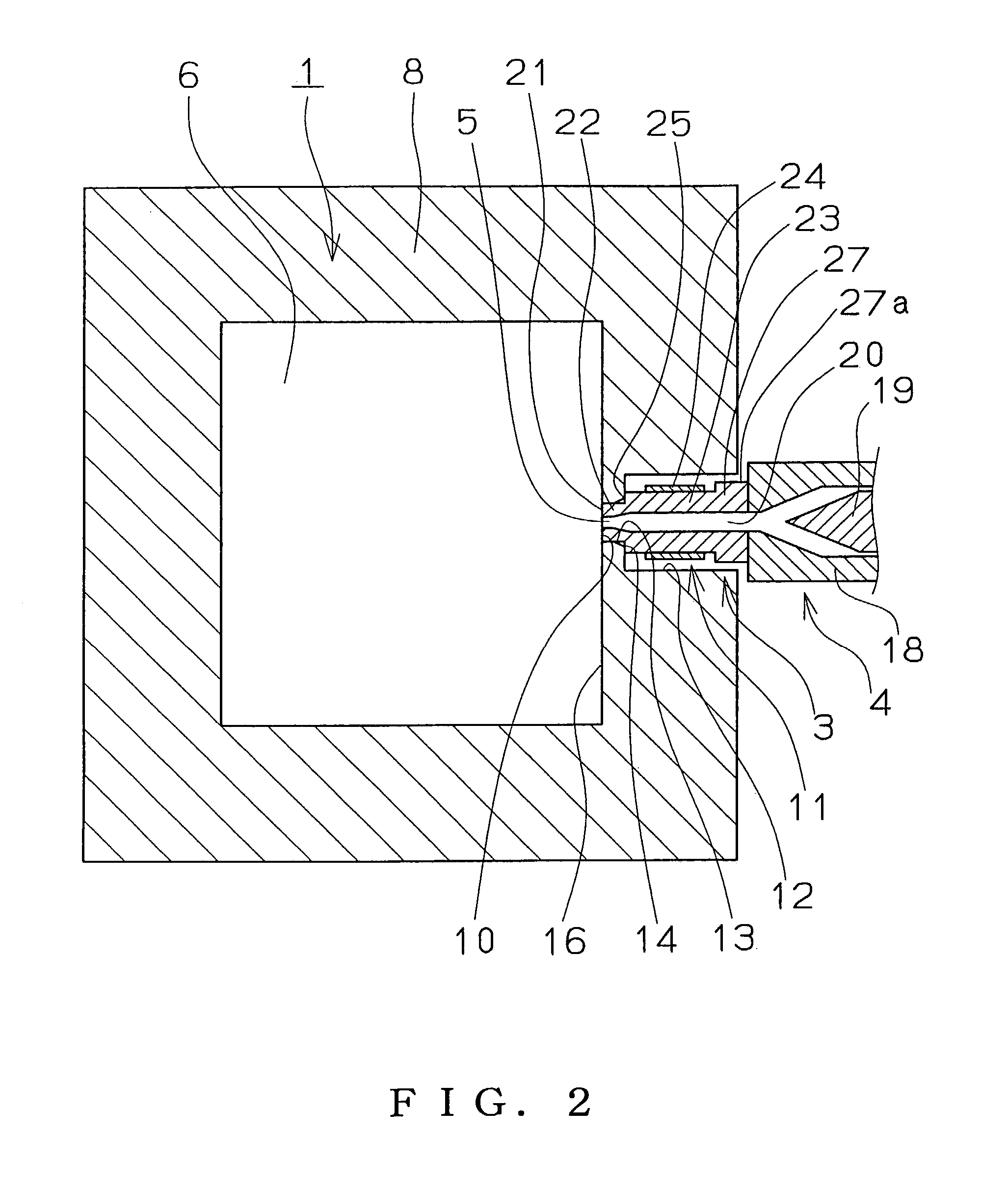
[0026]Hereinafter, the present invention will be described with reference to FIGS. 1–5. FIG. 1 is a cross-sectional view of an injection compression molding apparatus according to the present invention. FIG. 2 is a cross-sectional view taken on line A—A of FIG. 1. FIG. 3 is a perspective view showing a state in which a movable die is moved to the open position in the injection compression molding apparatus according to the present invention. FIG. 4 is an operation-explanatory drawing of the injection compression molding apparatus according to the present invention. FIG. 5 is an explanatory drawing for describing nozzle positioning in an injection compression molding method according to the present invention.

[0027]First, an injection compression molding apparatus according to the present invention will be schematically described with reference to FIGS. 1–4, wherein a stationary die 1, that is a lower die, is secured to a stationary platen at one side on a bed (not shown). Opposed to ...


PUM

PropertyMeasurementUnit
Pressureaaaaaaaaaa
Volumeaaaaaaaaaa
Dimensionaaaaaaaaaa

Abstract

In an injection compression molding apparatus and an injection compression method according to the present invention, the structure of the dies can be simplified and a loss of resin as well as of heat due to solidification of the resin in the path at the time of molding can be eliminated. Further, injection pressure loss can be reduced when melted resin is injected into a cavity. A resin injection hole in a nozzle that is attached to an injection device is connected at a position between a stationary die and a movable die directly to the cavity that has a larger volume than a volume of a molded product by means of the movable die, melted resin is injected into said cavity directly from said resin injection hole by said injection device, then the movable die is moved, in the die closing direction, to reduce the distance of the connection between said resin injection hole and said cavity by means of a side wall of the movable die, and to reduce the volume of the cavity so as to compress said melted resin.

Description

BACKGROUND OF THE INVENTION[0001]1. Field of the Invention[0002]The present invention relates to an injection compression molding apparatus, an injection compression molding die, and an injection compression molding method wherein melted resin is injected, into a cavity that is formed by a stationary die and a movable die, from a nozzle attached to an injection apparatus and, then, the volume of the cavity is reduced, to compress the melted resin in the cavity, by moving the movable die toward the stationary die.[0003]In the present invention, the injection compression molding includes both a so-called injection compression molding that moves the movable die in the die opening direction by injecting the melted resin into the cavity and then moves the movable die in the die closing direction again to compress the melted resin in the cavity, and a so-called injection press molding that injects the melted resin into the cavity while the movable die is stopped at a predetermined open po...

Claims


Application Information

Patent Timeline
IPC IPC(8): B29C45/18B29C45/26B29C45/17B29C45/20B29C45/56B29C45/70
CPCB29C45/1781B29C45/561B29C45/20B29C45/56
Inventor OYAMA, YOSUKE
Owner MEIKI
Why Eureka
Try Eureka