Shoulder replacement

a shoulder and prosthesis technology, applied in the field of shoulder replacement prosthesis, can solve the problems of pain or discomfort for patients, lack of mobility in the joint, and inability to replicate the anatomical configuration of the replacement shoulder,

Inactive Publication Date: 2010-11-18
BOROWSKY KEITH
View PDF2 Cites 11 Cited by
  • Summary
  • Abstract
  • Description
  • Claims
  • Application Information

AI Technical Summary

Benefits of technology

[0016]The longitudinal band of each of the four connection devices is used to define a cage to prevent longitudinal movement of the tuberosities, or counter the line of pull of the tendons in whatever plane they assume. The longitudinal band is preferably secured under the flange, passes

Problems solved by technology

A problem with the known shoulder replacement prostheses is that the positioning of the muscles and tendons in the replacement shoulder does not replicate the anatomical configuration.
Furthermore, movement of the tuberosities is often not s

Method used


Image

  • Shoulder replacement
  • Shoulder replacement
  • Shoulder replacement

Examples


Embodiment Construction

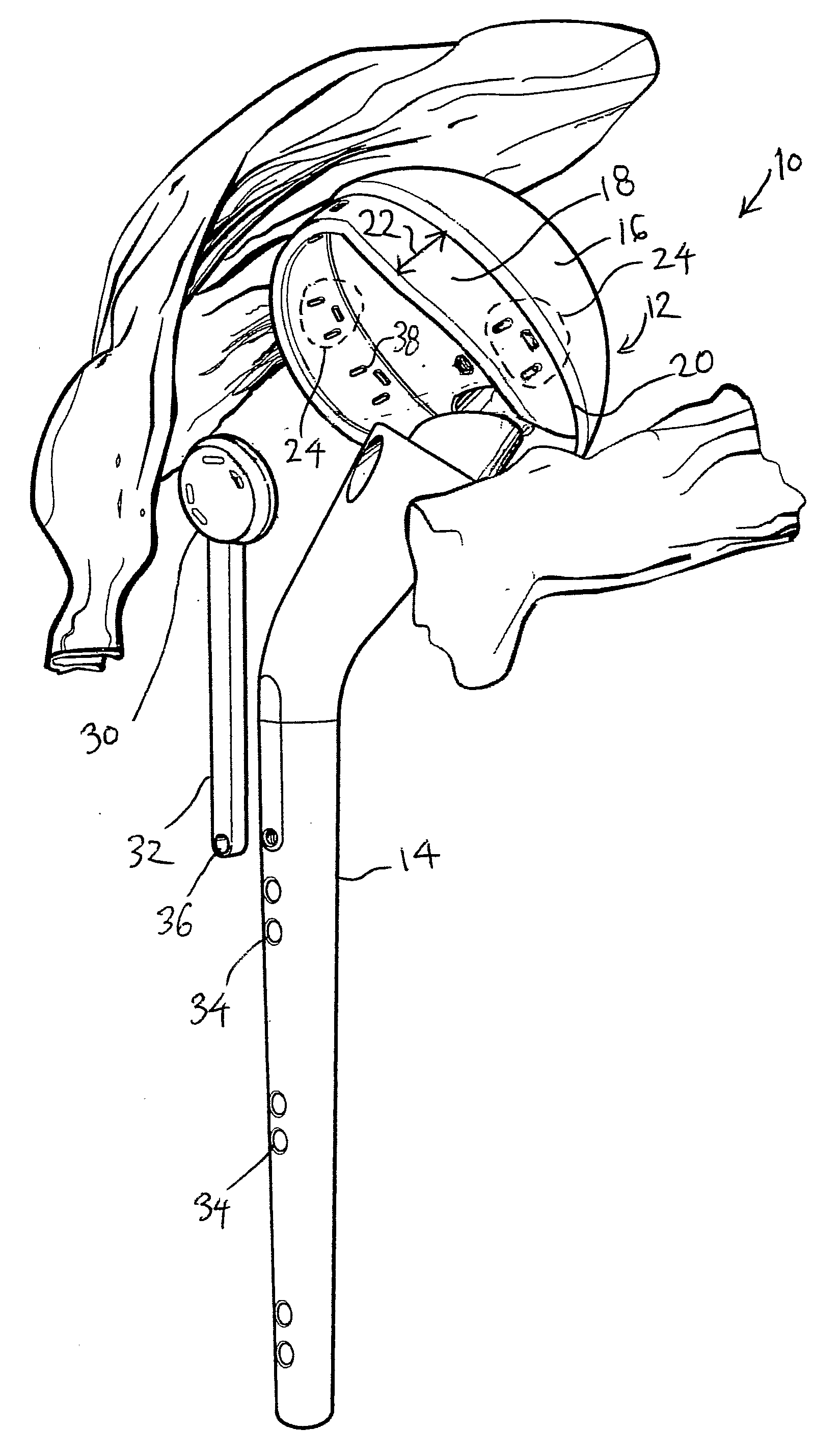
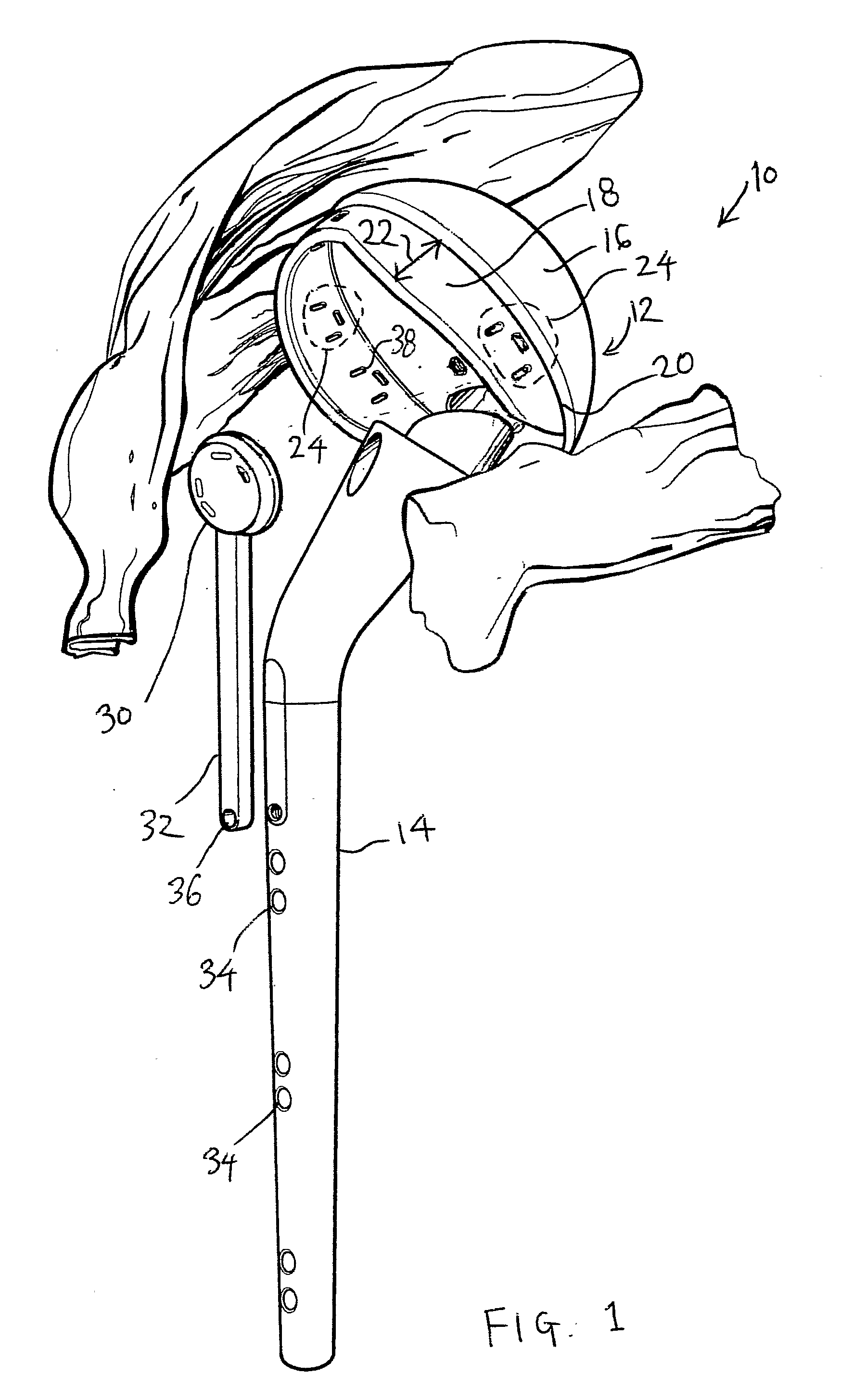
[0027]FIG. 1 shows the main components of the prosthesis of the invention.

[0028]The prosthesis 10 comprises a head 12 for replacing the humeral head, and a connection shaft 14. The head has a domed portion 16 and a flange 18 extending or positioned from an end region 20 of the domed portion.

[0029]This end region 20 is the interface between the domed portion 16 and the flange 18, and corresponds to the limit of the cartilage surface of the humerus head. The end region thus defines the anatomical neck of the humeral head. The domed portion 16 corresponds in shape to the head of a conventional shoulder implant prosthesis. The shape of the end region 20 is essentially circular and lies in a plane, so that the domed portion has a shape which is essentially a portion of a sphere defined by dissecting a sphere with a plane.

[0030]The flange 18 extends or is positioned from this interface 20 and substantially defines a portion of a quasi-cylinder, which approximates the shape of insertion po...


PUM


Abstract

A shoulder replacement prosthesis has a head (12) for replacing the humeral head and a connection shaft (14). The head has a domed portion (16) and a flange (18) positioned at an end region of the domed portion, and the flange (18) has a width (22) which varies around the domed portion, having a greater width at a part corresponding to a region of the greater tuberosity than at a part corresponding to a region of the lesser tuberosity. The flange is provided with a plurality of connection portions (24) for securing the tendons attached to the tuberosities. By dimensioning the flange appropriately, the anatomical positioning of the tendon to bone connections can be more accurately replicated. In particular, the flange acts to bridge the so-called bare area of the humeral head. The flange (18) provides a firm immovable surface area to which connections can be made, for example by partridge bands of greater surface area and rigidity than conventional sutures. Bands may also pass to a clamp so that a plastic cage surrounds the tuberosities.

Description

FIELD OF THE INVENTION[0001]This invention relates to a shoulder replacement prosthesis.BACKGROUND OF THE INVENTION[0002]The invention is particularly concerned with shoulder replacement carried out following a shoulder fracture although its use may be extended to any condition requiring shoulder replacement. In the case of shoulder fracture injuries, a hemi-arthroplasty is typically carried out to replace only the ball portion of the humeral head.[0003]A conventional prosthesis comprises a head and a stem, and the head of the prosthesis corresponds in shape to the humeral head, in particular the cartilage surface of the humeral head. The stem of the prosthesis is inserted into the top of the humerus shaft, and it is known to provide connection points at the top of the prosthesis stem which enable the greater and lesser tuberosities to be secured to the prosthesis.[0004]The tuberosities are conventionally secured using sutures which are connected to the interface between the tuberos...

Claims


Application Information

Patent Timeline
IPC IPC(8): A61F2/40
CPCA61B17/842A61F2/0811A61F2/4014A61F2002/2835A61F2002/30433A61F2220/0075A61F2002/30574A61F2002/30578A61F2002/30784A61F2002/4025A61F2220/0041A61F2002/30462A61F2002/30593
Inventor BOROWSKY, KEITH
Owner BOROWSKY KEITH
Why Eureka
Try Eureka