
Method of magnetizing rare-earth magnet and rare-earth magnet

Active Publication Date: 2007-06-19
SUMITOMO SPECIAL METAL CO LTD
View PDF7 Cites 1 Cited by
  • Summary
  • Abstract
  • Description
  • Claims
  • Application Information

AI Technical Summary

Benefits of technology

[0008]The present invention has been conducted in view of the above-mentioned prior art. One of objects of the present invention is to provide a magnetizing method of, when a magnet which is disposed in a cylindrical manner is magnetized so as to form regions magnetized in directions opposite to each other, magnetizing the vicinity of the regions in a predetermined direction more surely than in the prior art. Another object of the present invention is to provide a magnet magnetized by such a magnetizing method and a high-performance rotating machine employing the magnet, especially a rotating machine in which adjustment of angle can be performed with good precision.
[0015]The rare earth magnet according to the invention is magnetized by using any one of the above-mentioned magnetizing methods, so that the magnet has superior magnetic properties.
[0019]The rotating machine according to the present invention is provided with the rare earth magnet produced by the above-mentioned production method, so that the rotating machine has superior properties, and is suitable used for a valve opening control apparatus, or the like.

Problems solved by technology

It was found that when the magnets 5 and 6 used in a rotor of the above-mentioned motor 10 were magnetized in a condition where they were disposed in a cylindrical manner, or an integrally formed cylindrical magnet was magnetized, a conventional magnetization in which a magnetic field was applied once in a diametrical direction caused a problem that a boundary portion between regions magnetized in directions opposite to each other (corresponding to the magnets 5 and 6 in FIG. 5) was not sufficiently magnetized.
As a result, it may be difficult to adjust the angle of a rotating machine with good precision, or the performance of the rotating machine may not be sufficiently exercised.

Method used


Image

  • Method of magnetizing rare-earth magnet and rare-earth magnet
  • Method of magnetizing rare-earth magnet and rare-earth magnet
  • Method of magnetizing rare-earth magnet and rare-earth magnet

Examples


Embodiment Construction

[0025]Hereinafter, with reference to the drawings, an embodiment of a magnetizing method for a rare earth magnet according to the present invention will be described. The present invention is, however, not limited to the embodiment described below.

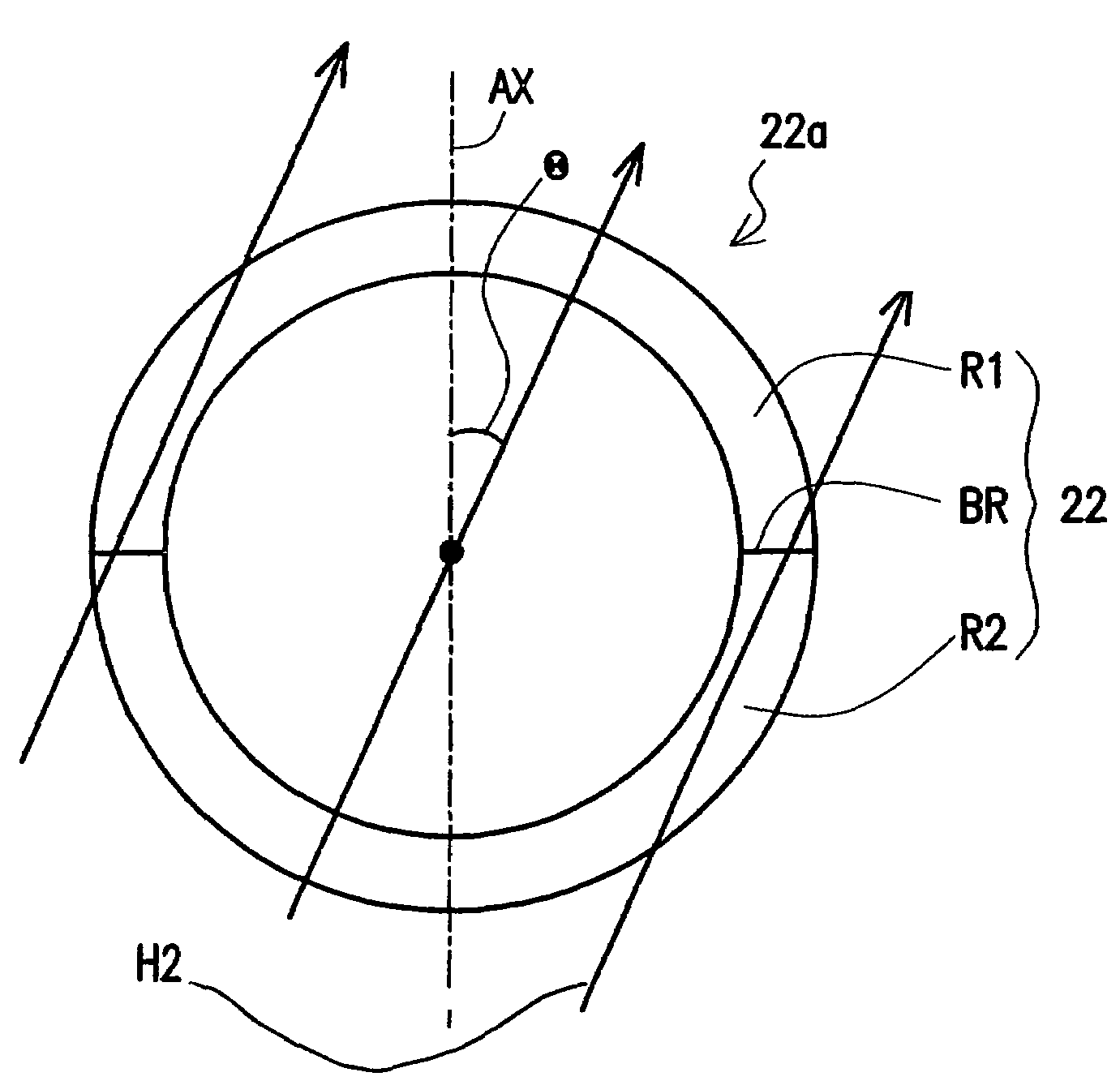
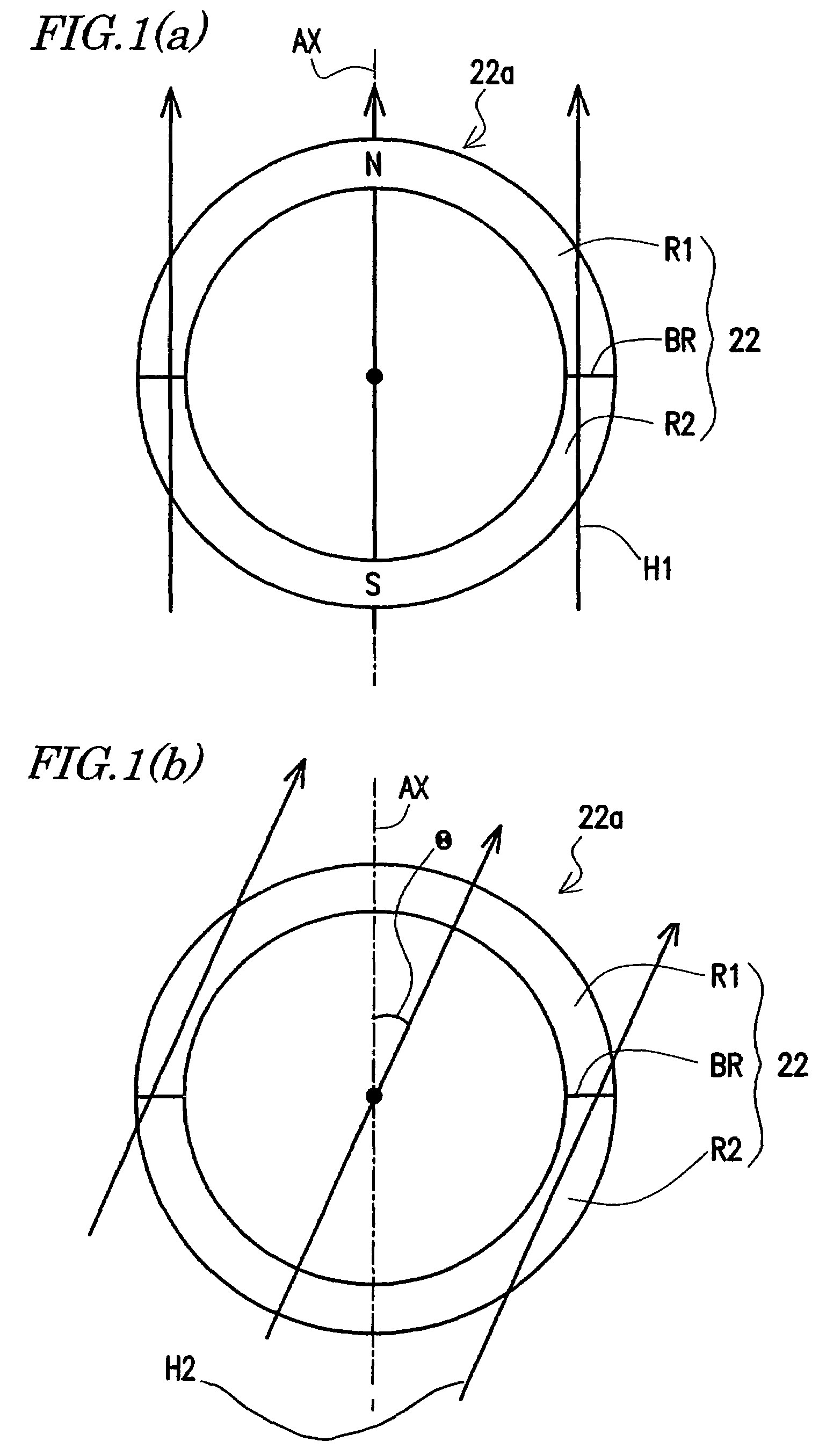
[0026]The magnetizing method for the rare earth magnet according to the present invention includes at least two magnetizing steps as shown in FIGS. 1(a) and (b).

[0027]First, a rare earth magnet (for simplicity, one before magnetization is also referred to as “a magnet”) 22 disposed so as to form a cylinder 22a is prepared. The rare earth magnet 22 may be a rare earth magnet integrally formed, or may be a magnet in which a plurality of segment magnets are fixed to a surface of a columnar rotor (Step (a)).

[0028]Next, by applying a first external magnetic field H1 to the rare earth magnet 22, a first region R1 magnetized from an inner side to an outer side of the cylinder 22a and a second region R2 magnetized from the outer side to the inner ...


PUM

PropertyMeasurementUnit
Angleaaaaaaaaaa
Angleaaaaaaaaaa
Angleaaaaaaaaaa

Abstract

The method of the present invention includes a step of preparing a rare earth magnet 22 disposed for forming a cylinder 22a, a first magnetizing step of applying a first external magnetic field H1 to the rare earth magnet 22, thereby forming a first region R1 magnetized from an inner side to an outer side of the cylinder 22a and a second region R2 magnetized from the outer side to the inner side, and a second magnetizing step of applying a second external magnetic field H2 so that an external magnetic field component forming an angle of more than 0° and less than 50° with a direction of the external magnetic field component applied in the first magnetizing step to a boundary between the first region R1 and the second region R2.

Description

TECHNICAL FIELD [0001]The present invention relates to a magnetizing method for a rare earth magnet, and more particularly to a magnetizing method suitable for magnetizing a rare earth magnet which is used in a fixed condition to a rotor in a rotating machine.BACKGROUND ART [0002]Presently, as rare earth magnets, two kinds of magnets, i.e., rare earth / cobalt-based magnets and rare-earth / iron / boron-based magnets are widely used in various fields.[0003]Among them, the rare-earth / iron / boron-based magnets (hereinafter, referred to as “R-T-(M)-B magnets”, R is a rare earth element including Y, T is Fe or a mixture of Fe with Co and / or Ni, M is an additive element (at least one of Al, Ti, Cu, V, Cr, Ni, Ga, Zr, Nb, Mo, In, Sn, Hf, Ta, W, for example), and B is boron or a mixture of boron with carbon) exhibit the highest maximum magnetic energy product in various kinds of magnets, and they are relatively cheep. For these reasons, the R-T-(M)-B magnets are actively adopted to various electr...

Claims


Application Information

Patent Timeline
IPC IPC(8): H01F1/053H01F7/06H01F13/00H02K15/03
CPCH01F13/003H02K15/03Y10T29/4902
Inventor SAKAGUCHI, EIJIMORIMOTO, HITOSHI
Owner SUMITOMO SPECIAL METAL CO LTD
Features
  • Generate Ideas
  • Intellectual Property
  • Life Sciences
  • Materials
  • Tech Scout
  • Unparalleled Data Quality
  • Higher Quality Content
  • 60% Fewer Hallucinations
Learn More