

Serial printing with multiple torsional hinged MEMS mirrors
a technology of torsional hinges and mirrors, applied in printing, instruments, optics, etc., can solve the problems of oscillating frequency differences, the speed of the rotating photosensitive drum cannot be synchronized or adjusted with respect to one of the four resonant mirrors, and the difficulty of resonant torsional hinged mirrors
- Summary
- Abstract
- Description
- Claims
- Application Information
AI Technical Summary
Benefits of technology
Problems solved by technology
Method used
Image

Examples
Embodiment Construction
[0019]The making and using of the presently preferred embodiments are discussed in detail below. It should be appreciated, however, that the present invention provides many applicable inventive concepts that can be embodied in a wide variety of specific contexts. The specific embodiments discussed are merely illustrative of specific ways to make and use the invention, and do not limit the scope of the invention.
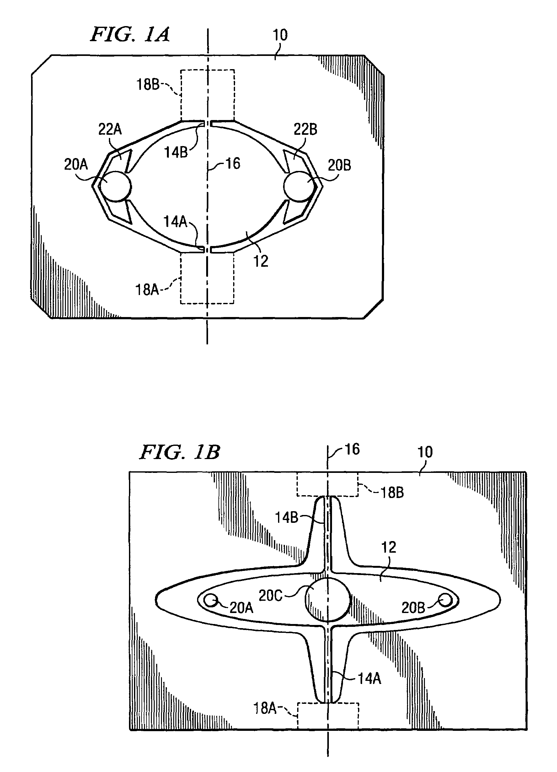
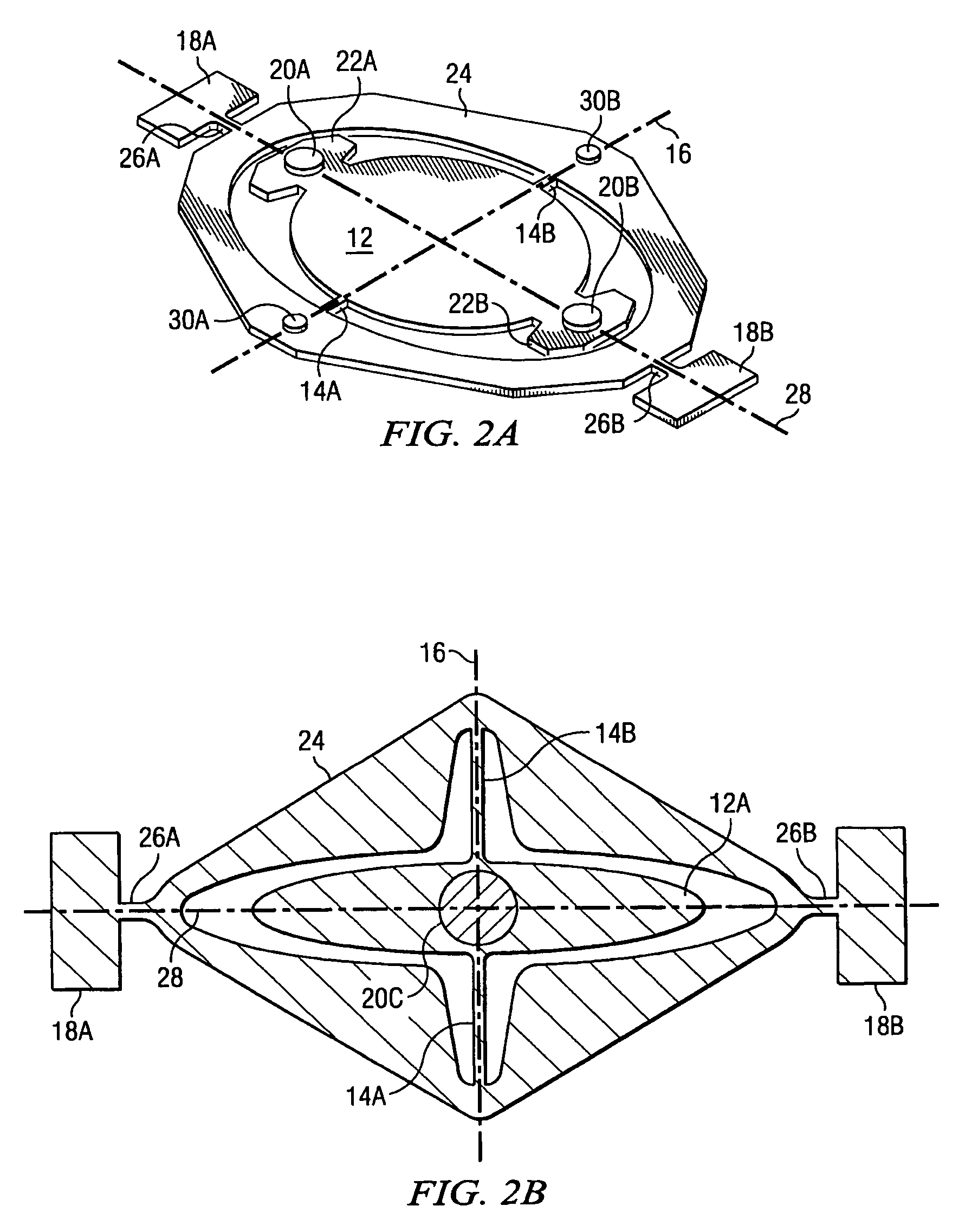
[0020]MEMS (mechanical electro mechanical) devices having torsional hinges to provide resonant oscillations are manufactured by Texas Instruments Incorporated of Dallas, Tex. Resonant torsional hinged mirrors have found increasing acceptance as drive engines or scan units for various types of display devices and especially laser printers. Further, various types of resonant torsional mirrors may be used in such printers. For example, a resonant torsional mirror may pivot around two orthogonal axis. That is, a first pair of hinges are provided for high-speed resonant oscillatio...
PUM
 Abstract
Description
Claims
Application Information