Disk drive system employing effective disk surface stabilization mechanism

a disk drive and stabilization mechanism technology, applied in the direction of digital signal error detection/correction, instruments, recording signal processing, etc., can solve the problem that the object-lens actuator of the pickup cannot cope with a large amplitude, the automatic disk replacement mechanism cannot identify particular disks, and it is difficult to create a stabilized condition at a portion. problem, to achieve the effect of preventing the generation of errors and eliminating the surface vibration of optical disks

Inactive Publication Date: 2007-06-19
RICOH KK
View PDF9 Cites 13 Cited by
  • Summary
  • Abstract
  • Description
  • Claims
  • Application Information

AI Technical Summary

Benefits of technology

[0013]An object of the present invention is to provide an optical disk drive which solves the above-mentioned problems, can eliminate surface vibration of the optical disk by means of air force, can enable high-density record in case recording / reproduction is performed using an optical disk in a form of flexible sheet, and can prevent generating of error such as that caused due to slide contact to the object lens, optical information recording device, optical information reproducing device, and a disk cartridge used therefor.
[0016]a stabilization part, stabilizing vibration of the optical disk along the rotation axis direction of the optical disk by means of pressure difference of air flow created according to Bernoulli's law at a portion of the optical disk on which information writing / reading is performed, provided on a side of the optical disk opposite to a side on which information recording / reproducing is performed,
[0018]By providing the areas of the optical disk having no pressure difference created due to the air flow according to Bernoulli's low caused by the stabilization part, these areas acting as ‘escape’, and thus, it is possible to effectively reduce repulsive force occurring in the portion at which the stabilization effect should be performed on by means of the stabilization part. Thus, the stabilization effect there can be increased effectively.
[0023]Thereby, it is possible to effectively reduce the required movable range of the object lens, thus to reduce the weight of the optical head, and, thereby, to achieve the optical head having improved high-frequency response performance.
[0026]Thereby, it is possible to accurately control an area on the optical disk at which the stabilization effect caused by the stabilization guide member is most effectively performed on, and, thus, it is possible to perform recording / reproducing on a desired area of the optical disk which area is best stabilized from surface vibration, and, thus, to achieve high-quality information recording / reproducing.
[0030]Thereby, it is possible to properly and positively control surface vibration on the optical disk by means of the stabilization guide member at an arbitrary portion of the optical disk which information recording / reproducing is performed.

Problems solved by technology

Specifically, as each disk 1 is thin, and intervals between the respective disks 1 are narrow, it may be difficult for the automatic disk replacement mechanism to identify particular disks.
Furthermore, thereby, the object-lens actuator of this pickup should not cope with a large amplitude, low frequency movement, and instead, should have a high-rigidity elastic member (spring) for supporting the actuator.
However, according to such a device, when the flexible disk bends, bending force strongly functions from the upstream and downstream sides, and, thereby, it may be difficult to create a stabilized condition at a portion at which a laser beam for recording / reproducing is applied.
When it is too thick, a properly flexibility cannot be provided, while when it is too thin, the sheet-like record disk 101 may be destroyed due to stress applied in acceleration / deceleration thereof.
Such a larger abnormal vibration may be a suddenly occurring large pulse caused by collision of the sheet-like record disk and guide member, for example.
Although the object lens 102a may collide with the sheet-like record disk 101 in case it is of a rigid body like a conventional optical disc due to surface vibration of the disk, and thereby, error may occur.
In addition, the specification of optical disks are intricately related to many factors, and thus, it can be said that it is impossible to find out a law concerning these factors.

Method used


Image

  • Disk drive system employing effective disk surface stabilization mechanism
  • Disk drive system employing effective disk surface stabilization mechanism
  • Disk drive system employing effective disk surface stabilization mechanism

Examples


first embodiment

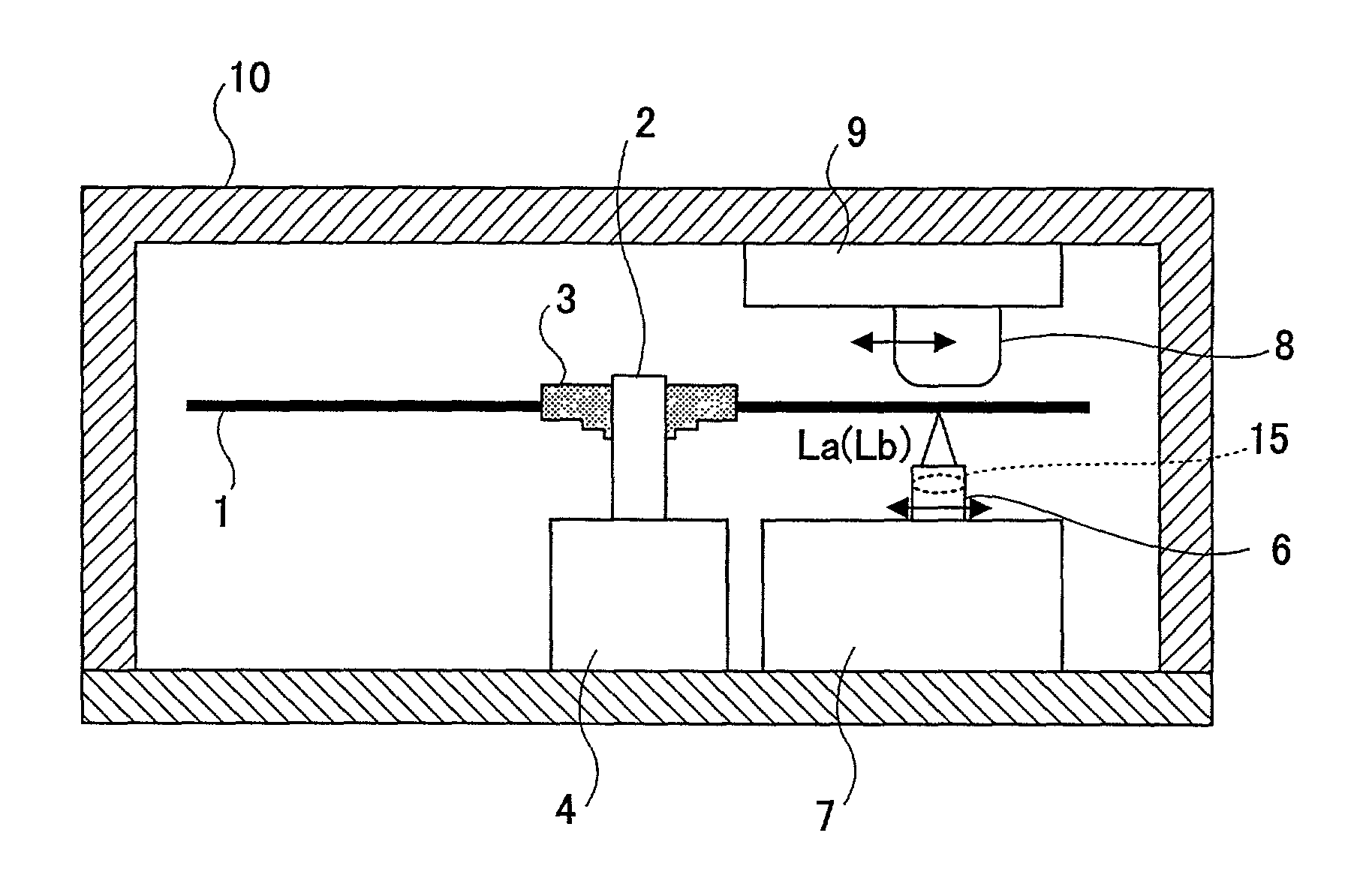
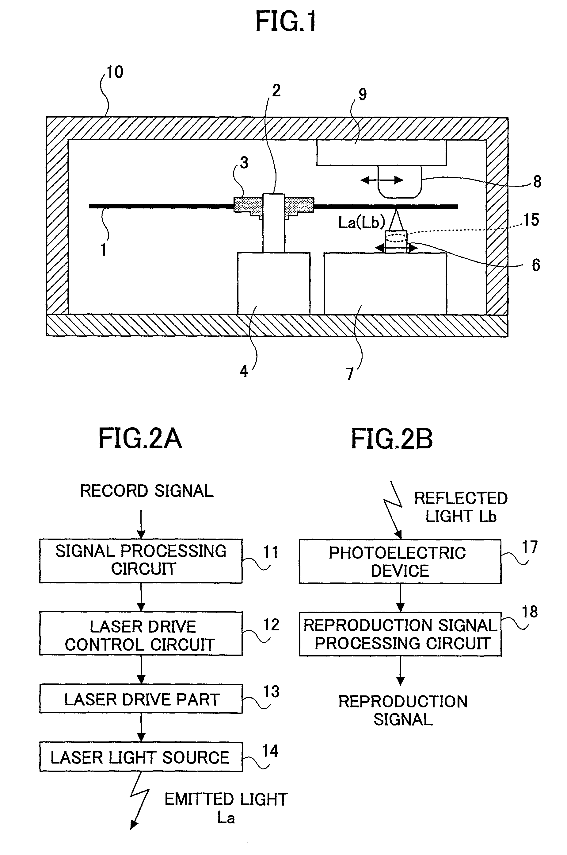
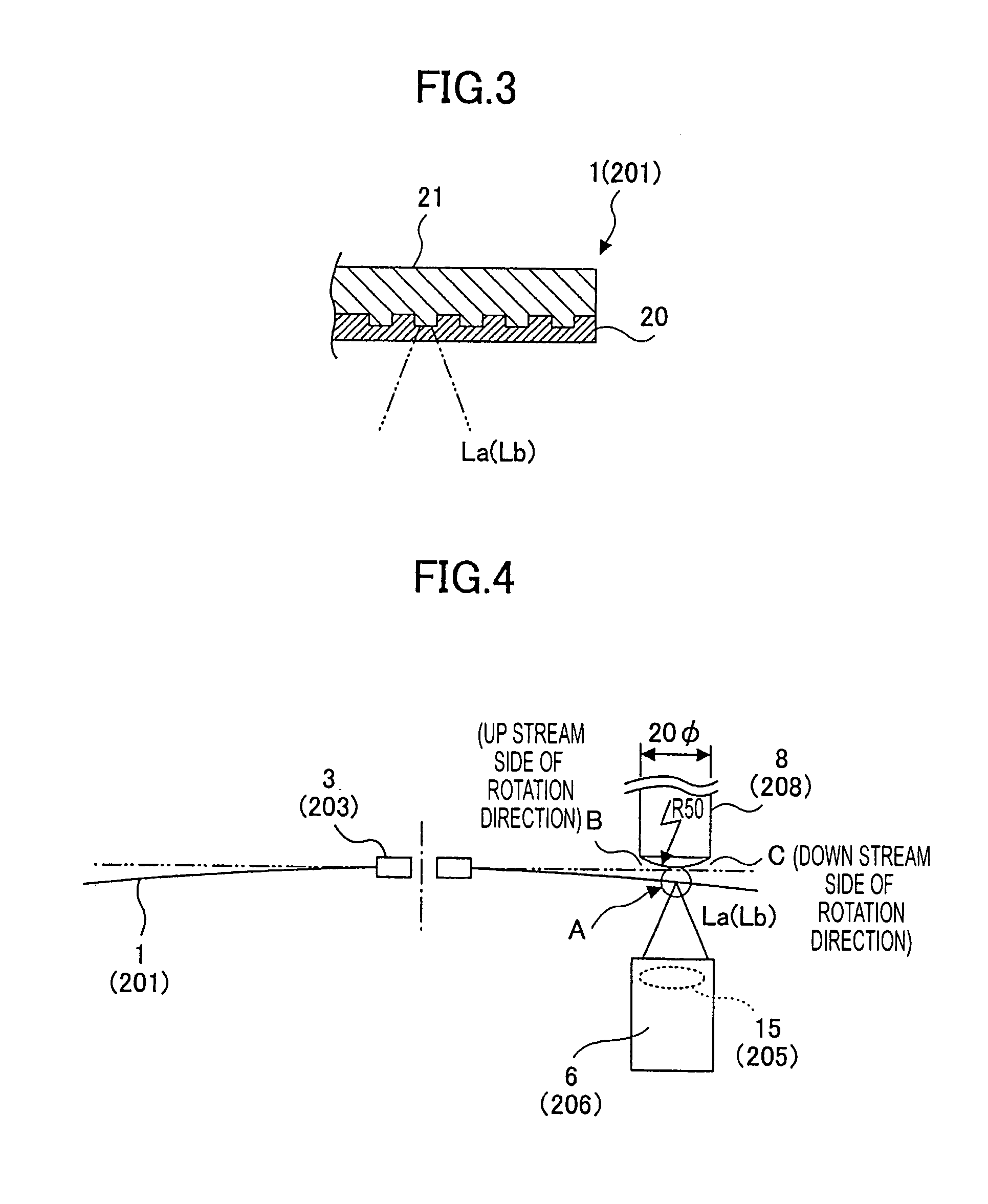
[0066]As shown in FIG. 1, in an optical information recording / reproducing device in the present invention, a sheet-like optical disk 1 has a flexibility, a spindle shaft 2 holds a hub 3 of the optical disk 1, a spindle motor 4 carries out rotation drive of the spindle shaft 2, an optical pickup 6 writes / reads information onto / from the optical disk 1, a positioning mechanism 7 for the pickup moves the optical pickup 6 along the radius direction of the optical disk 1, and a stabilization guide member 8 is provided on the opposite side from the optical pickup with respect to the optical disk 1, and prevents surface vibration of the optical disk 1. A positioning mechanism 9 moves the stabilization guide member 8 together with the optical pickup 6 along the radius direction of the optical disk 1. These respective members / components are held by a device body 10.

[0067]FIGS. 2A and 2B illustrate a recording unit and a reproducing unit both of which the above-mentioned optical pickup 6 acts....

second embodiment

[0099]FIG. 11 shows a side-elevational sectional view of an optical information recording / reproducing device in the present invention. In this configuration, the sheet of optical disk 1 is contained in a disk cartridge 27 having opening windows 26 and 26, this disk cartridge 27 is inserted into a predetermined position in the recording / reproducing device, shutters 28 and 28 are then opened by an operation unit not shown, the stabilization guide member 8 and optical pickup 6 are moved so that this member 8 and the optical pickup 6 are inserted therethrough, and thus, a state in which recording / reproduction is possible is created, as shown in FIG. 11.

[0100]As the disk cartridge 27, a common configuration can be employed, and, thus, it can be provided with a very low cost rise if any.

[0101]FIG. 12 shows a side-elevational sectional view of an optical information recording / reproducing device in a third embodiment of the present invention. In this configuration, the stabilization guide m...

third embodiment

[0102]Also in the third embodiment, a shutter 28 is moved by an operation unit not shown, so that the optical pickup 6 may be inserted through an opening window 26 opened widely thereby, and, thus, a state in which recording / reproduction is possible is created, as shown in FIG. 12.

[0103]According to the third embodiment, as the stabilization guide member 30 is built in the disk cartridge 30, the entire configuration of the recording / reproducing device can be made same as the conventional device for applying an optical disk of a rigid substrate. Thereby, it becomes easy to take compatibility with a disk drive system of the optical disk using such a rigid substrate.

[0104]FIG. 14 shows a plan view of a disk cartridge in a fourteenth embodiment of the present invention and FIG. 15 shows a side-elevational sectional view thereof taken along an A—A line shown in FIG. 14. This disk cartridge may be applied to an optical recording / reproducing device same as the first embodiment described ab...


PUM

PropertyMeasurementUnit
wavelengthaaaaaaaaaa
thicknessaaaaaaaaaa

Abstract

A stabilization part stabilizes surface vibration of a flexible optical disk along a rotation axis direction of the optical disk by means of pressure difference of air flow created according to Bernoulli's law at a portion on which information writing / reading is performed, provided on a side of the optical disk opposite to a side on which information recording / reproducing is performed. In this case, areas are provide on the upstream side and down stream side along the disk rotation direction of the portion of the optical disk which is stabilized by said stabilization part, said areas of the optical disk not having pressure difference created thereon by the air flow.

Description

BACKGROUND OF THE INVENTION[0001]1. Field of the Invention[0002]The present invention relates to a disk drive system employing a disk surface stabilization mechanism, and, in particular, an optical disk drive for carrying out rotation drive of an optical disk which is an optical information recording medium in a form of sheet which has a flexibility, an optical information recording device, an optical information reproduction device, and a disk cartridge used therefor.[0003]2. Description of the Related Art[0004]Optical disks are demanded to store mass digitized data, as digitization of television broadcasting starts in recent years. A basic method of improving recording density on the optical disks is to reduce the diameter of a beam spot used for recording / reproduction information onto / from the optical disk.[0005]For this reason, it is effective to shorten in wavelength of light used for recording / reproduction, and also, it is effective to enlarge numerical aperture NA of an objec...

Claims


Application Information

Patent Timeline
Patent Type & Authority Patents(United States)
IPC IPC(8): G11B11/03G11B17/32G11B5/55G11B7/0037G11B33/08
CPCG11B5/5582G11B7/08G11B7/0946G11B7/0956G11B11/1055G11B19/042G11B19/2081G11B21/12G11B23/0035G11B23/005G11B33/08G11B7/0037G11B7/0953
Inventor ONAGI, NOBUAKIAMAN, YASUTOMOMURATA, SHOZO
Owner RICOH KK
Why Eureka
Try Eureka