Nail clipper

a nail clipper and clipper body technology, applied in the field of nail clippers, can solve the problems of hindering the use of the nail clipper, easy to lose the cap, inconvenient and dangerous to carry, etc., and achieve the effects of convenient portability, convenient operation and small siz

Inactive Publication Date: 2007-06-26
WONG WAI YIP
View PDF23 Cites 17 Cited by
  • Summary
  • Abstract
  • Description
  • Claims
  • Application Information

AI Technical Summary

Benefits of technology

[0004]In view of the aforesaid disadvantages now present in the prior art, the present invention provides a nail clipper which is safe and reliable, small in size, convenient to carry, easy to fold for storage, equipped with a durable pressing piece that does not deform and is susceptible of a lower production cost.

Problems solved by technology

Most of the nail clippers are inconvenient and dangerous to carry because their cutting edges do not bite together for storage.
The simplest method is to provide a cap to cover the cutting edges, but it is easy to lose the cap.
Attaching the cap onto the clipper body can avoid losing the cap but it hinders the use of the nail clipper.
Although this method is more practical, as the pressing piece is persistently pressed by the cover plate when folded for storage, prolonged use renders the pressing piece becoming deformed or losing elasticity and so the pressing piece cannot function eventually.
In order for the nail clipper to be simple to use and for the cutting edges thereof to bite together for storage, many technical proposals require many parts and components, more complex assembling and higher production costs and are inconvenient to use.
To nail clippers such goods for daily use which are small in size and easily lost and have to be discarded once the cutting edges become blunt, it is difficult for the market to widely accept nail clippers which are too expensive and complicated to use.
The prior art therefore cannot fully satisfy the demands of the consuming public.

Method used


Image

  • Nail clipper
  • Nail clipper
  • Nail clipper

Examples


Embodiment Construction

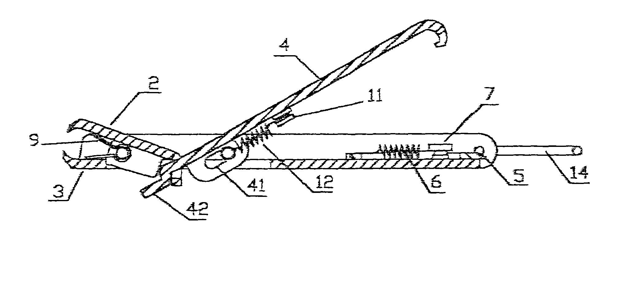
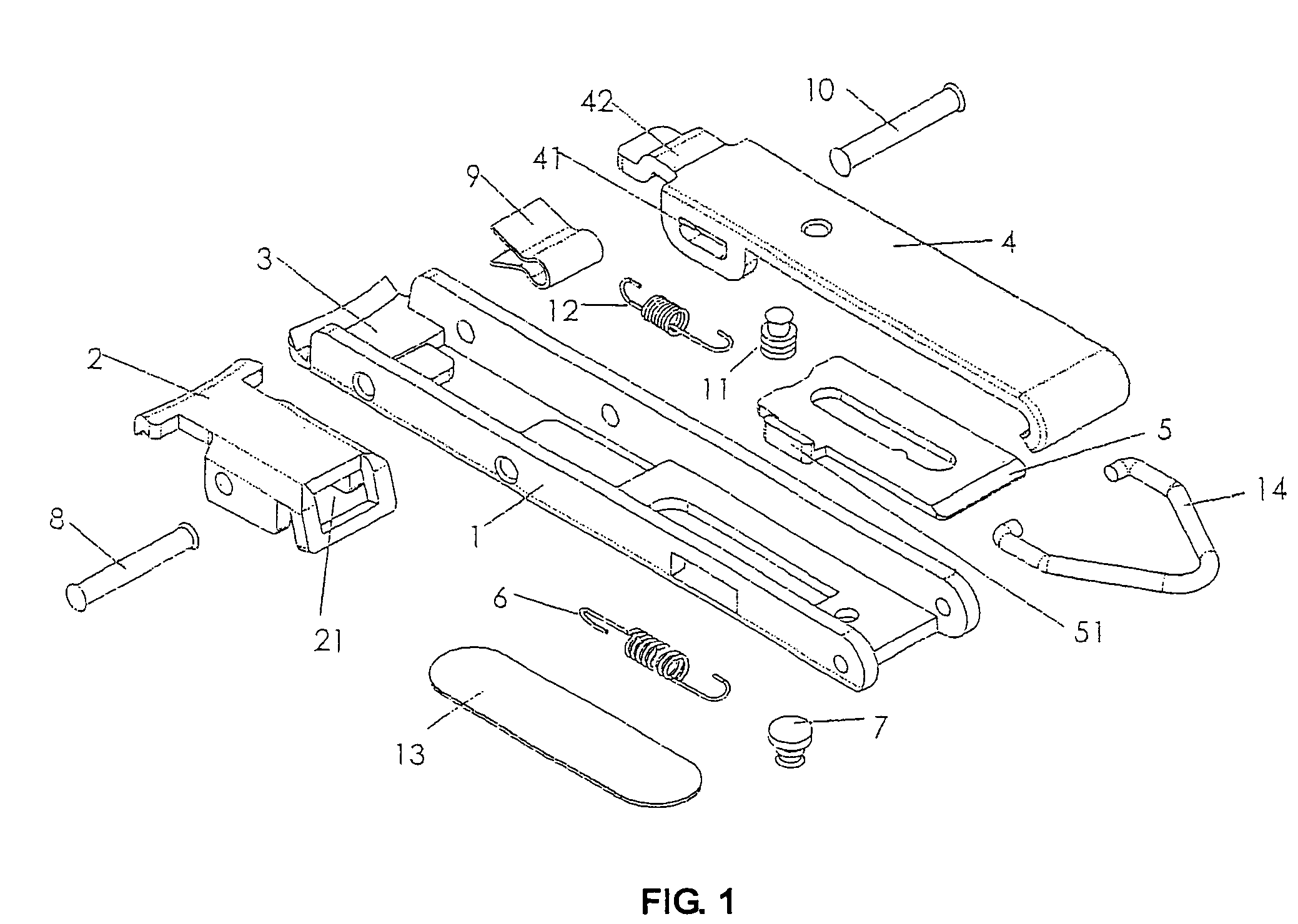
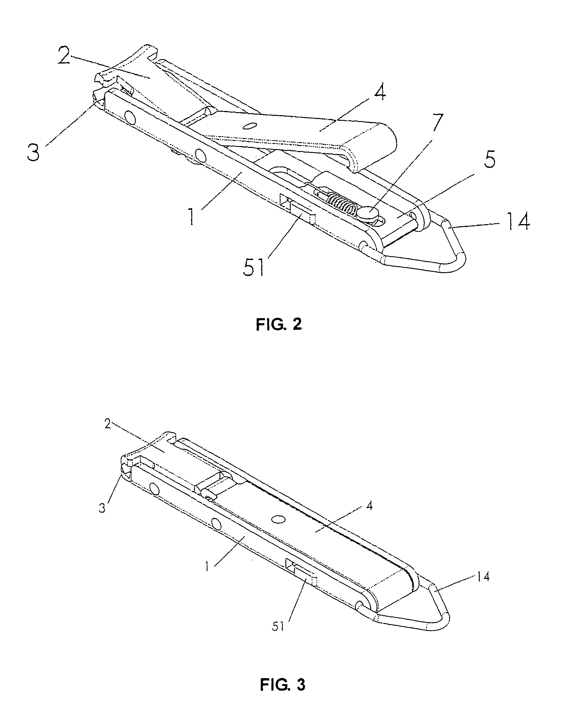
[0023]As illustrated in FIGS. 1 to 3, the nail clipper comprises a body 1, an upper cutting part 2, a lower cutting part 3 and a pressing piece 4.

[0024]The body 1 is in the shape of a box which is open at the top and is open at the bottom near the front end, and has the lower cutting part 3 at its front end and a sliding locking piece 5 at its rear end.

[0025]The sliding locking piece 5 is connected by a return spring 6 and a peg 7 to the rear end of the body 1 and has a pulling button 51 which protrudes outside the body 1 and can bring along the sliding locking piece 5 to slide inwards.

[0026]The upper cutting part 2 is movably connected to the front end of the body 1 through a pivot 8, and through a spring piece 9 it is connected to and can bite with the lower cutting part 3. The position of the cutting edge at the front end of the upper cutting part 2 corresponds to the position of the cutting edge of the lower cutting part 3, and the upper cutting part 2 has an opening 21 at its r...


PUM


Abstract

A nail clipper includes a body, an upper cutting part, a lower cutting part and a pressing piece. The body is a box shape which is open at the top and at the bottom near the front end, and has the lower cutting part at its front end and a sliding locking piece at its rear end. The sliding locking piece has a pulling button which protrudes outside the body. The upper cutting part is movably connected to the front end of the body and has an opening at its rear end. The pressing piece is movably connected through a pivot to the middle front part of the body and its rear end bends downwards and can hook onto the sliding locking piece.

Description

BACKGROUND OF THE INVENTION[0001]The present invention relates to a nail clipper and more particularly pertains to a portable nail clipper as a tool for manicure and pedicure.[0002]There are various technical proposals relating to nail clippers. Most of the nail clippers are inconvenient and dangerous to carry because their cutting edges do not bite together for storage. There are some nail clippers with the cutting edges biting together for storage. The simplest method is to provide a cap to cover the cutting edges, but it is easy to lose the cap. Attaching the cap onto the clipper body can avoid losing the cap but it hinders the use of the nail clipper. Another method is to add a cover plate which is connected to the clipper body. The cover plate is structured to press the pressing piece when folded for storage, thereby locking the cutting edges to a position that they bite together. Although this method is more practical, as the pressing piece is persistently pressed by the cover...

Claims


Application Information

Patent Timeline
Patent Type & Authority Patents(United States)
IPC IPC(8): A45D29/02A45D29/04
CPCA45D29/02A45D29/04
Inventor WONG, WAI YIP
Owner WONG WAI YIP
Why Eureka
Try Eureka