Adjustable apparatus for hair clipper

a technology of adjustable apparatus and hair clipper, which is applied in the direction of metal working apparatus, etc., can solve the problems of limited adjustment of the rotary wheel, and achieve the effects of simple assembly process and operation, low production cost, and promotion of the electric hair cutter industry

Active Publication Date: 2007-06-26
YAO WOODY
View PDF7 Cites 35 Cited by
  • Summary
  • Abstract
  • Description
  • Claims
  • Application Information

AI Technical Summary

Benefits of technology

[0007]The primary object of the invention is to provide an adjustable apparatus for a hair clipper, in that the adjustable apparatus allows a user to operate a rotary wheel to the left or right with small forces applied by one hand, such that distances of an upper blade being moved forward or backward are controlled for accomplishing objects of operating the electric hair cutter with ease and convenience.
[0008]The other object of the invention is to provide an adjustable apparatus for a hair clipper, in that the adjustable apparatus promotes advancement of the electric hair cutter industry apart from having simple assembly process and operation as well as low production costs.
[0009]To accomplish the aforesaid objects, an adjustable apparatus for a hair clipper comprises a cutter assembly joined to a front end of an electric hair cutter housing, a pushing block and a rotary wheel. The cutter assembly is consisted of a stationary blade seat and an upper blade assembly, wherein the upper blade assembly is provided at an upper surface of the stationary blade seat. The upper blade assembly has a upper blade seat, and a locating spring secured at an interior of a spring housing. Two ends of the locating spring are joined with an upper surface of the upper blade seat for interlocking effects between the upper blade seat and the spring housing. A spring blade is provided between the upper blade seat and the spring housing, and is butted against the spring housing, such that the spring blade is generated with a restoring force from compression when the spring housing is moved forward. A fastening block is extended from a rear end of the pushing block, which is for pivotally connecting the pushing block to a rear end of the stationary blade seat and is butted against the spring housing for allowing the pushing block to propel the spring housing forward. The rotary wheel is devised with an adjustment region having a step-like adjustment portion, and is joined to a front end of the electric cutter housing, in a way that an edge of the rotary wheel is protruding out of the electric cutter housing for adjustment by turning. The fastening block of the pushing block is accommodated in the adjustment region of the rotary wheel, and is lodged at one of the steps of the adjustment region, such that turning of the rotary wheel is limited within the adjustment region. When a user turns the rotary wheel toward higher-level steps of the step-like adjustment portion, the fastening block of the pushing block is affected by turning of the rotary wheel to simultaneously propel the spring housing and the upper blade seat forward to further locate the spring housing and the upper blade seat. At this point, the spring blade is compressed to produce a restoring force from the forward movement of the spring housing. When the rotary wheel is turned toward lower-steps of the adjustment portion, the pushing block is moved backward with a certain distance to liberate the spring housing that is then also moved backward using the restoring force of the spring, thereby accomplishing adjustment of the upper blade.

Problems solved by technology

The fastening block of the pushing block is accommodated in the adjustment region of the rotary wheel, and is lodged at one of the steps of the adjustment region, such that turning of the rotary wheel is limited within the adjustment region.

Method used


Image

  • Adjustable apparatus for hair clipper
  • Adjustable apparatus for hair clipper
  • Adjustable apparatus for hair clipper

Examples


Embodiment Construction

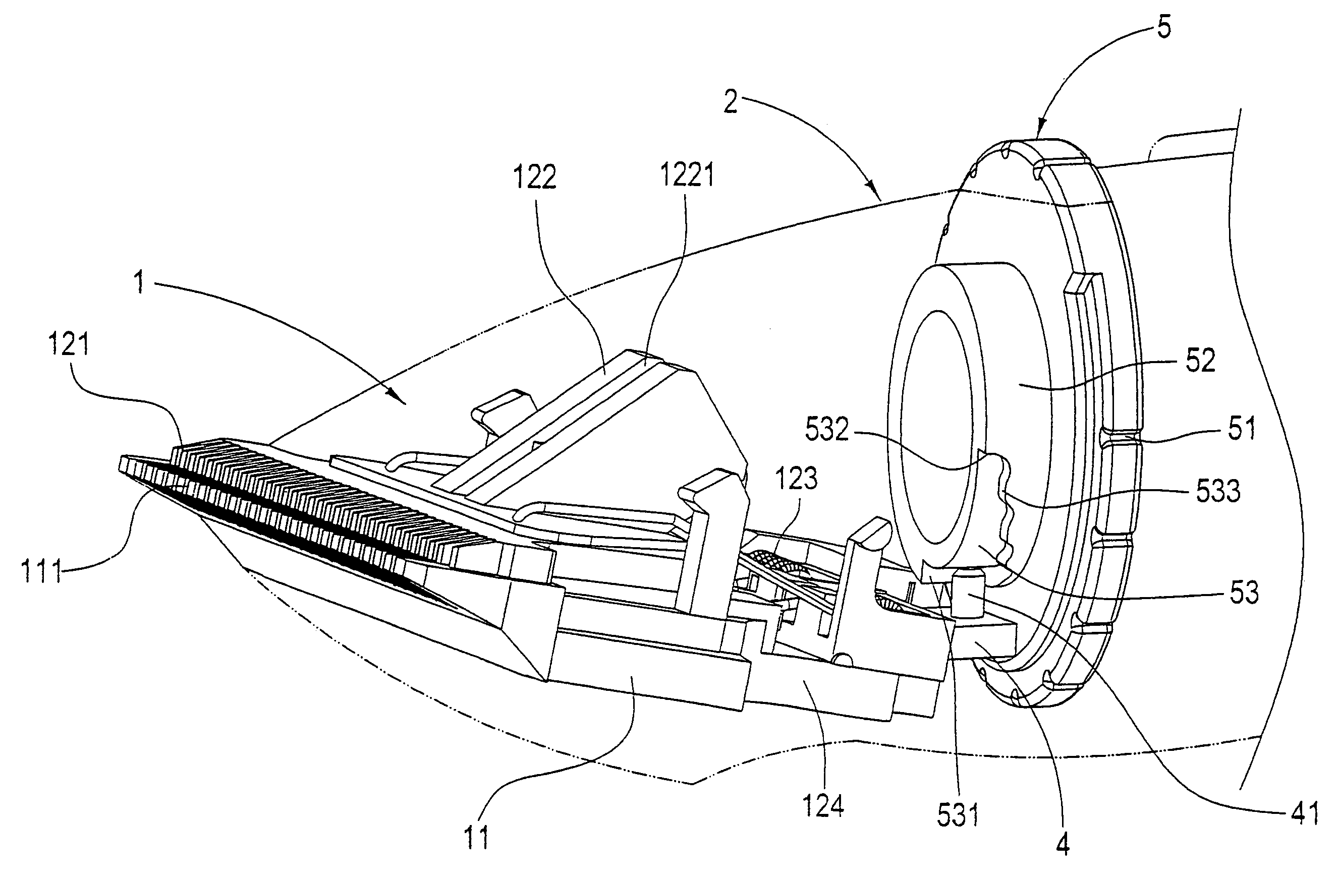
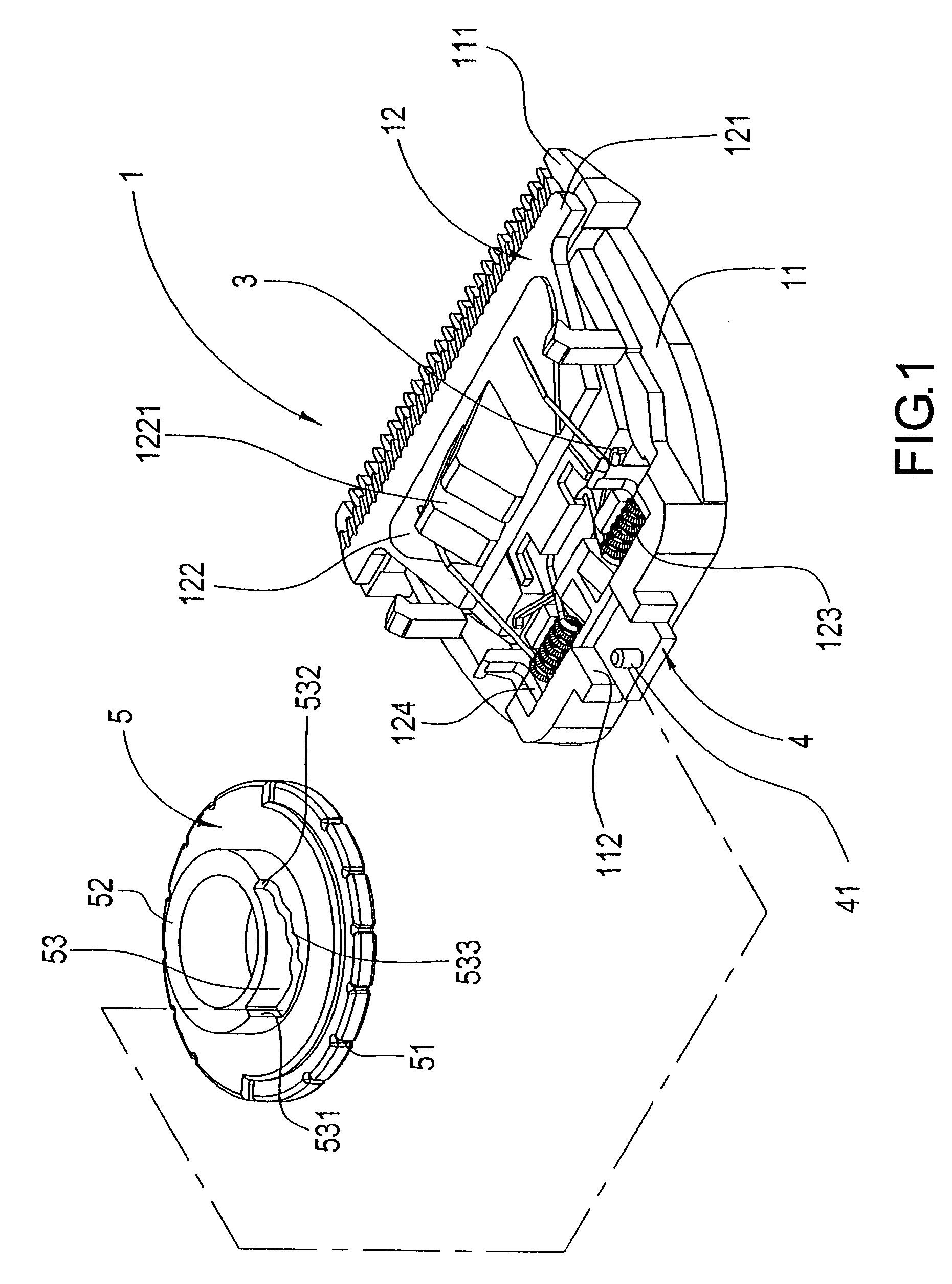
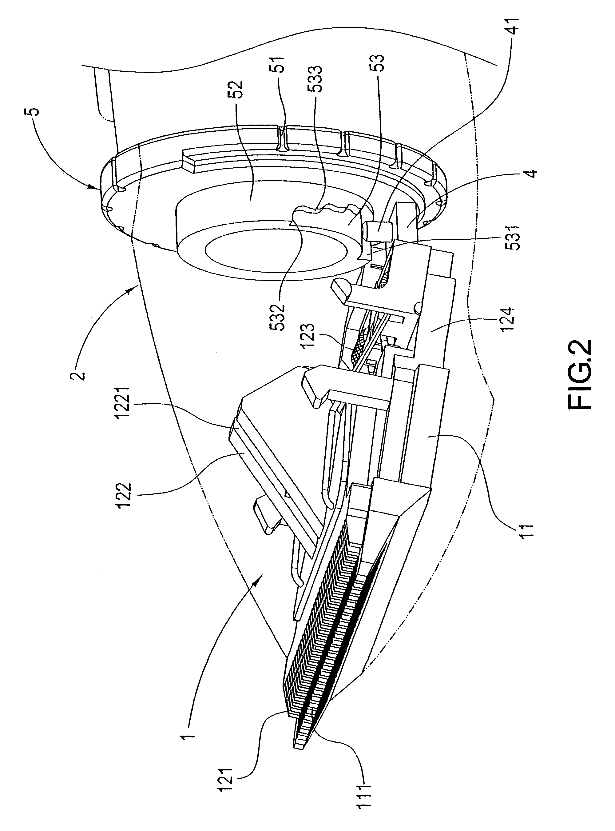
[0015]Referring to FIG. 1 and FIG. 2, an adjustable apparatus for a hair clipper according to the invention comprises:

[0016]a cutter assembly 1 joined to a front end of an electric hair cutter housing 2, and consisted of:

[0017]a stationary blade seat 11, which has a connected stationary blade 111 having a cutting edge thereof projecting from a front end of the electric hair cutter housing 2, and a sliding channel 112 extended from a rear end thereof; and

[0018]an upper blade assembly 12 having an upper blade 121, an upper blade seat 122, and a locating spring 123 secured at an interior of a spring housing 124; wherein, the upper blade seat 122 is provided with a fastening groove 1221 for joining two ends of the locating spring 123 with an upper surface of the upper blade seat 122, such that the upper blade seat 122, the locating spring 123 and the spring housing 124 are joined to form one body having interlocking effects; the spring housing 124 is joined to an upper surface approachi...


PUM


Abstract

The invention discloses an adjustable apparatus for adjusting an upper blade position of a hair clipper to further adjust the hair cut length. The upper blade is connected to a blade spring. The blade spring is placed in a spring housing. The spring housing is connected to a pushing block. The pushing block is connected to a rotary wheel. Therefore, the position of the upper blade is adjustable by moving the rotary wheel.

Description

BACKGROUND OF THE INVENTION[0001](a) Field of the Invention[0002]The invention relates to an adjustable apparatus for a hair clipper, and more particularly, to an adjustable apparatus for a hair clipper, in that the adjustable apparatus moves an upper blade assembly using a pushing block driven by a rotary wheel and restores the upper blade assembly to an original position thereof using a spring blade, thereby moving the upper blade as desired.[0003](b) Description of the Prior Art[0004]Electric hair cutters are often used in household-styled barber shops and beauty parlors. To meet customers' needs on hair lengths, a length adjuster is necessarily installed to a tip section of a blade of the electric hair cutter in order to control lengths of hair being cut. However, due to various needs of different customers, a diversity of length adjusters is required, and tremendous usage inconveniences are resulted. Also, economical values are disadvantaged for that length adjusters of numerou...

Claims


Application Information

Patent Timeline
Patent Type & Authority Patents(United States)
IPC IPC(8): B26B19/20
CPCB26B19/06B26B19/205B26B19/3846
Inventor YAO, WOODY
Owner YAO WOODY
Why Eureka
Try Eureka