Reciprocating cutting tool with orbital action

a reciprocating cutting and cutting tool technology, applied in the field of hand-held power tools, can solve the problems of insufficient mechanical force applied to the rear of the blade, inability to achieve potential cutting improvement of orbital cutting, and introduction of flex and play, so as to achieve the effect of generating the motion of the orbital blade and more direct application of orbital for

Active Publication Date: 2007-06-26
CREDO TECH CORP
View PDF12 Cites 26 Cited by
  • Summary
  • Abstract
  • Description
  • Claims
  • Application Information

AI Technical Summary

Benefits of technology

[0008]The above-listed needs are met or exceeded by the present reciprocating cutting tool, such as a jigsaw, which overcomes the limitations of the current technology. Among other things, the present tool is designed to provide operational support for the plunger, and more effective generation of the orbital blade motion. The former advantage is obtained in part by a hemispherical bearing connected to the plunger which supports orbital action. The latter advantage is obtained in part by mounting a swivel bracket on the foot plate for more direct application of orbital force to the point of cutting action. Also, a linkage is provided which selectively enables both scroll cutting and orbital cutting motion.

Problems solved by technology

A drawback of this location is that insufficient mechanical force is applied to the rear of the blade to provide strong cutting action during the orbital stroke.
In this manner, the potential cutting improvements of orbital cutting are not achieved.
Another drawback of this control location is that due to the relatively long length of the plungers, the provision of the pendulum-like orbital option often introduces flex and play in the operation of the plunger.
This relatively large amount of flex makes it more difficult to accurately control the movement of the lower end of the plunger, which is also the attachment point of the blade.
The result is cutting inefficiency and / or inaccuracy.
Additionally, the placement of the swivel support at the tool housing results in another drawback, the swivel support prevents the cutting device from being able to do scrolling and orbital cutting with the same tool through a selector switch.

Method used


Image

  • Reciprocating cutting tool with orbital action
  • Reciprocating cutting tool with orbital action
  • Reciprocating cutting tool with orbital action

Examples


Embodiment Construction

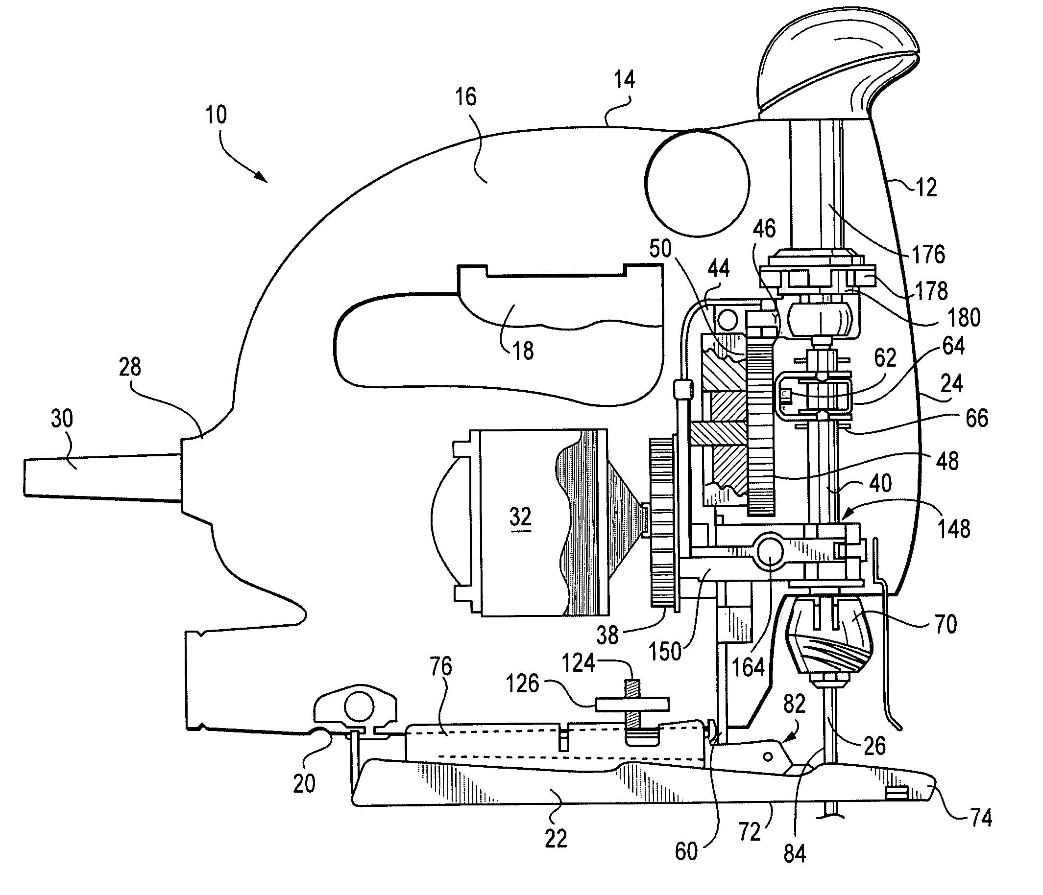
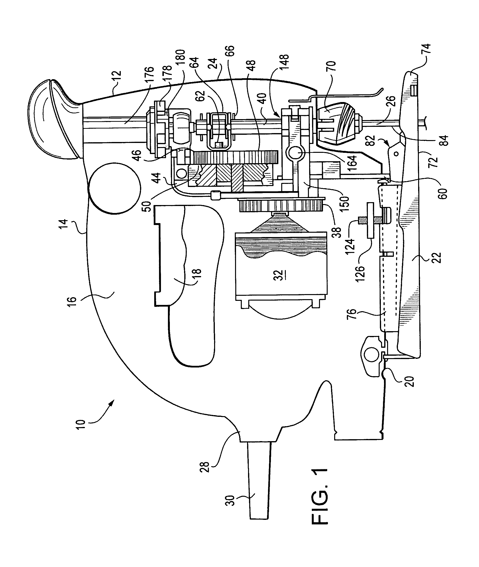
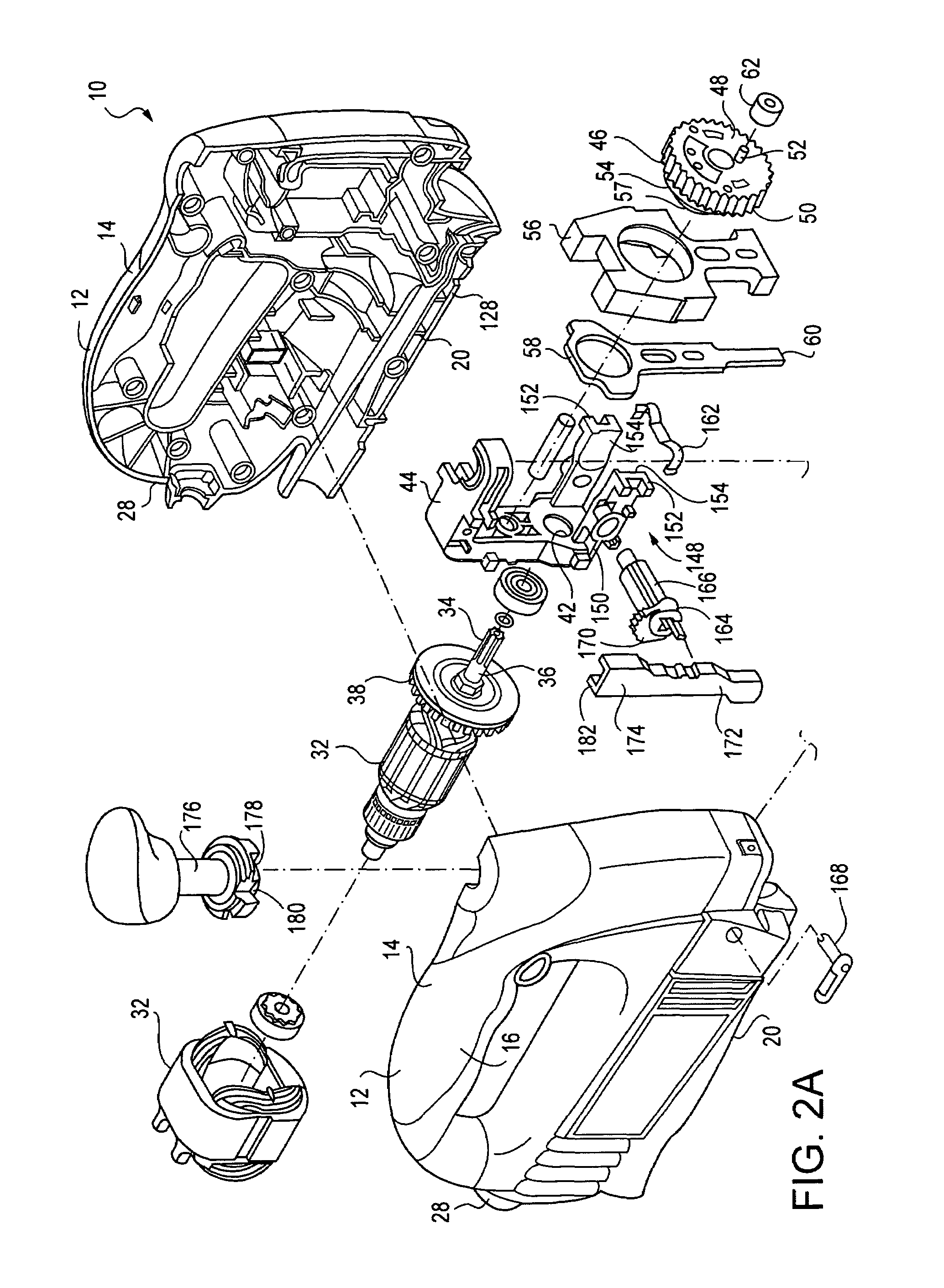
[0013]Referring now to FIGS. 1, 2A and 2B, a reciprocating cutting tool suitable for use with the present invention is generally designated 10. In the preferred embodiment, the tool 10 is a jigsaw, however other reciprocating cutting tools are contemplated as benefiting from the present invention, including but not limited to saber saws.

[0014]In the present invention, the term “orbital cutting motion” refers to the blade of the saw following a general elliptical cutting stroke. Orbital cutting motion has been found to achieve greater cutting efficiency from power tools, in that it resembles the motion of an individual putting relatively greater force or weight against a saw during a cutting stroke than a return stroke. In the case of jigsaws, the cutting edge of the blade is configured for cutting mainly in an upwardly directed cutting stroke. During orbital cutting motion, the otherwise vertically reciprocating blade is provided with a forward movement component as it ascends, and ...


PUM

PropertyMeasurementUnit
forceaaaaaaaaaa
mechanical forceaaaaaaaaaa
lengthaaaaaaaaaa

Abstract

A reciprocating cutting tool configured for orbital cutting, includes a housing, a power source disposed in the housing, a main linkage connected to the power source and to a blade for driving the blade in a vertically reciprocating motion, a foot plate connected to the housing and including a portion in operational relationship to the blade, a swivel bracket connected to the foot plate and disposed to exert an orbital force to a rear edge of the blade. A plunger is secured within the housing and connected to the linkage for reciprocal, pivotal and rotational movement, and has an end configured for receiving a blade. A selector mechanism for selecting at least between pivotal and rotational movement of the plunger, wherein the pivotal movement relates to orbital blade motion, and the rotational movement relates to scrolling blade motion.

Description

BACKGROUND OF THE INVENTION[0001]The present invention relates generally to hand-held power tools employing reciprocating working action, such as jigsaws or saber saws, and particularly to jigsaws capable of orbital cutting action.[0002]It is known to provide jigsaws with orbital motion, in which the normally vertically reciprocating blade exerts a forward or lateral component of the cutting stroke. This type of orbital motion has been known to provide more effective cutting action.[0003]One design criterion of such saws is that the main plunger, the shaft-like component to which the blade is attached and which reciprocates to provide the cutting motion, is also permitted a specified degree of forward and rearward play to effect orbital motion.[0004]It is also known to provide such tools with scroll cutting capability for making intricate designs and other projects involving tight cutting parameters. To date, tools that were capable of both scroll cutting or orbital cutting had a me...

Claims


Application Information

Patent Timeline
Patent Type & Authority Patents(United States)
IPC IPC(8): B27B11/02B23D49/16
CPCB23D49/165B23D49/167
Inventor TAM, RAMONMORENO, JAIMEELLIS, BRIAN
Owner CREDO TECH CORP
Why Eureka
Try Eureka