Method and apparatus for evaporative cooling of a cooling fluid
a technology of cooling fluid and cooling method, which is applied in the field of method and apparatus for evaporative cooling of cooling fluid, can solve the problems of increasing the external volume of the cooling tower, the cooling effect of the compensation water is not sufficient to cool the relatively large amount of inflowing air, and the increase in the wet-bulb temperature of the inlet, so as to maximize the cooling efficiency of the cooling apparatus
- Summary
- Abstract
- Description
- Claims
- Application Information
AI Technical Summary
Benefits of technology
Problems solved by technology
Method used
Image
Examples
first embodiment
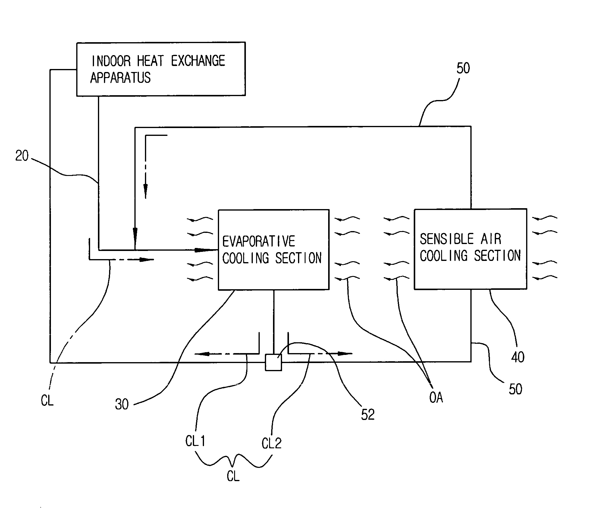
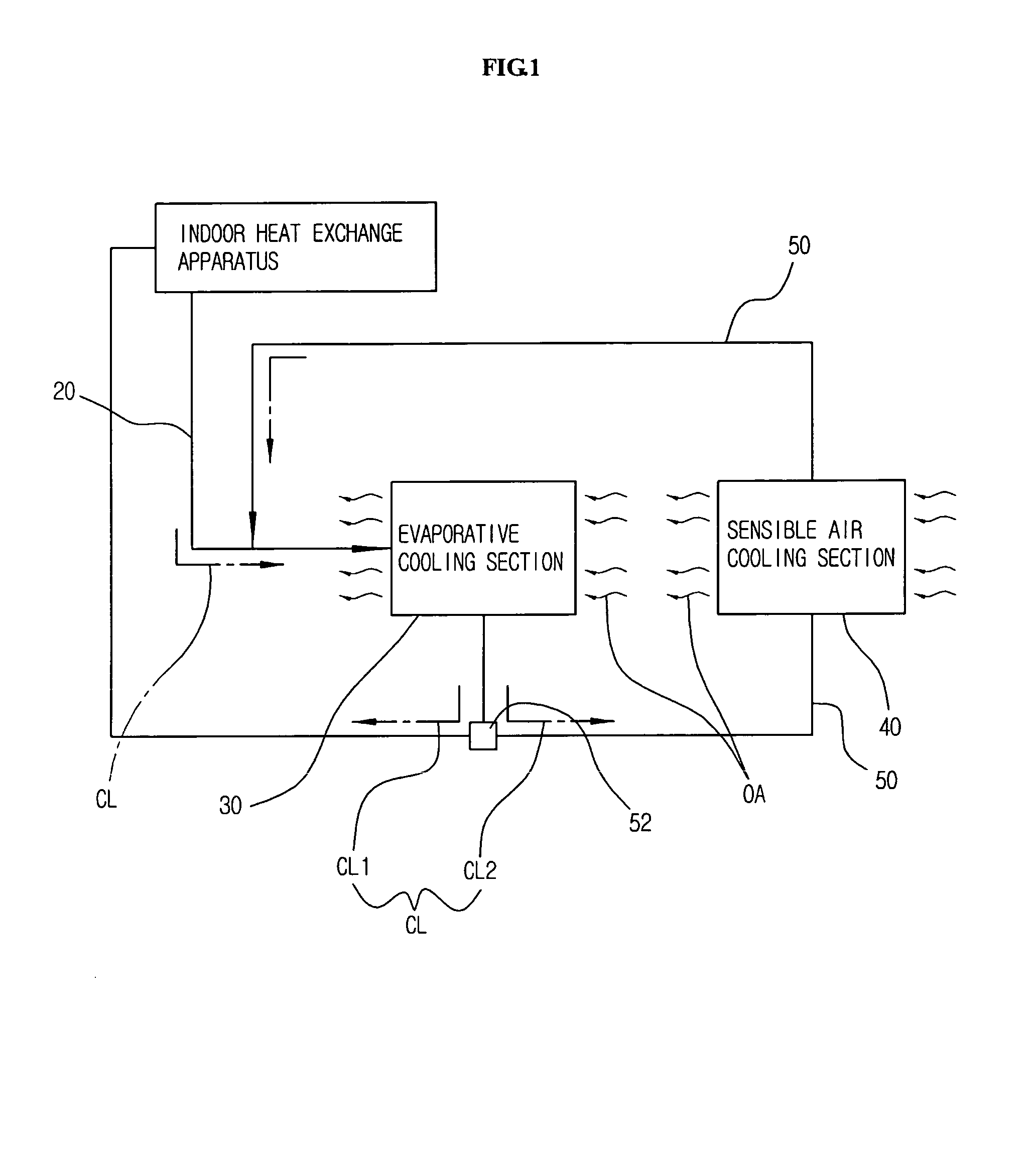
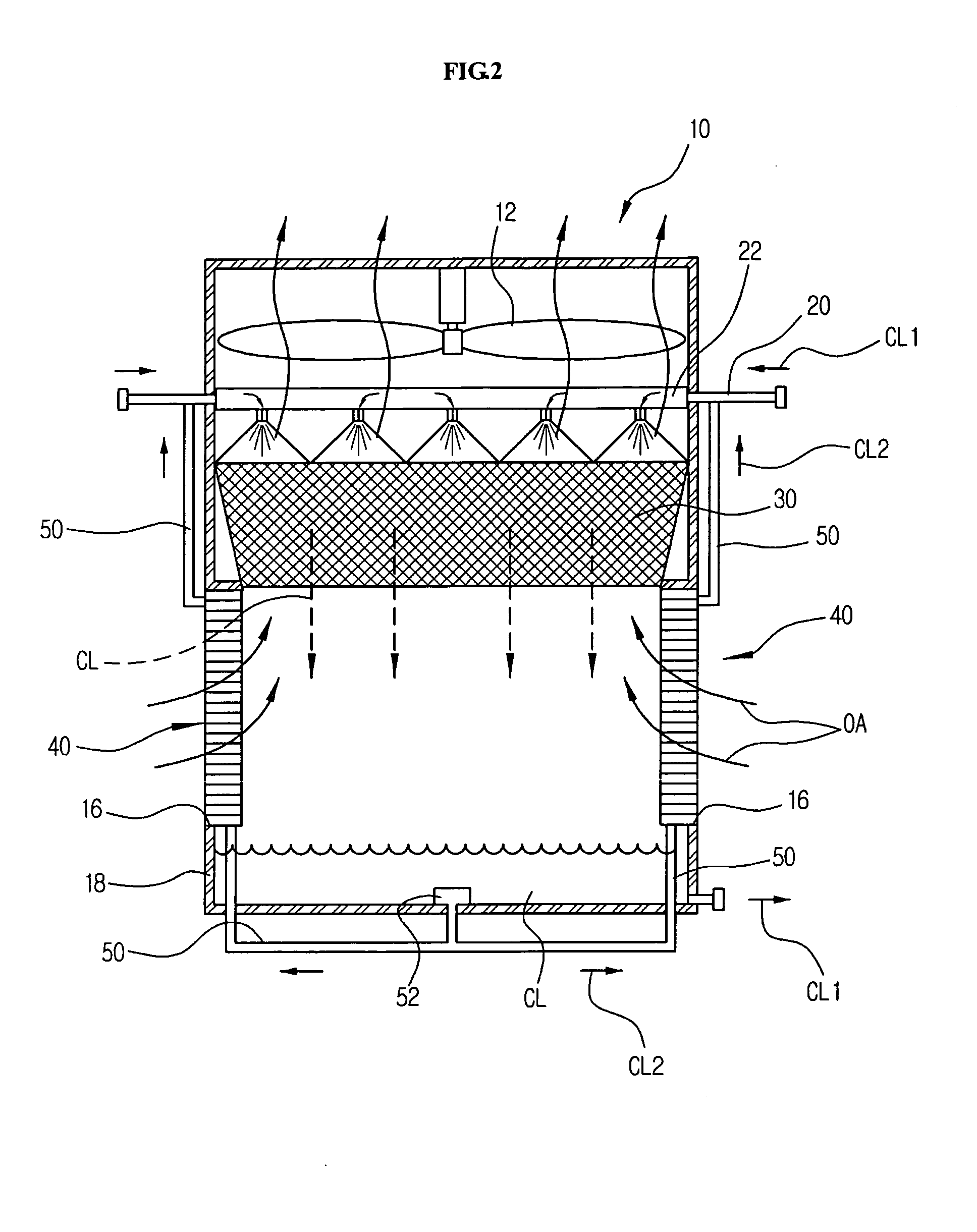
[0052]FIG. 2 shows a constitution of an evaporative cooling apparatus according to a preferred first embodiment of the present invention. Referring to FIG. 2, the apparatus for evaporative cooling of a cooling fluid comprises the evaporative cooling section 30 installed in a cooling tower (=an evaporative cooler) for evaporatively cooling a cooling fluid (CL); the sensible air-cooling section 40 installed at the air inlet 16 of the evaporative cooler 10 for sensibly cooling the outside air (OA) by indirect contact of the second cooling fluid (CL2), which was extracted from the cooling fluid (CL1) having been evaporatively cooled in the evaporative cooling section 30; and a circulating member 50 piped in such a manner that the second cooling fluid (CL2), which has flown out of the sensible air-cooling section 40, re-circulates into the evaporative cooling section 30.
[0053]Herein, the cooling fluid (CL), which has been evaporatively cooled as it passes through the evaporative cooling ...
second embodiment
[0083]Meanwhile, FIG. 5 shows a preferred second embodiment according to the present invention.
[0084]As shown in FIG. 5, the preferred second embodiment has the same constitution and operation as the preferred first embodiment except that the cooling fluid (CL) indirectly contacts with the outside air (OA) in the evaporative cooling section 30.
[0085]In other words, as shown in FIG. 5, the evaporation water (EW) instead of the cooling fluid (CL) is supplied to the distribution pipe 22 by means of an EW circulating pump 72 and an EW circulating pipe 70, distributed over the evaporative cooling section 30 and passes there through it. The evaporation water (EW) drips down from the evaporation cooling section 30, collects in the collection sump 18 and is supplied back to the evaporative cooling section 30.
[0086]The cooling fluid (CL) flows through the heat exchange tubes 32 installed in the evaporative cooling section 30 instead of being distributed over the evaporative cooling section 3...
third embodiment
[0088]Meanwhile, FIG. 6 shows a preferred third embodiment according to the present invention.
[0089]As shown in FIG. 6, this preferred third embodiment has the same constitution and operation principle as the first embodiment or the second embodiment except that a controlling valve 60 is disposed in the circulating member 50 in order to control the amount of flow of the second cooling fluid (CL2).
[0090]The controlling valve 60 is preferably installed in the circulating member 50 between the circulating pump 52 and the sensible air-cooling section 40, so that it can control the amount of flow of the second cooling fluid (CL2) directed to the sensible air-cooling section 40. The controlling valve 60 is controlled by a separate controlling means and can be constituted of a well-known electronic valve for controlling an amount of flow.
[0091]If the flow amount of the second cooling fluid (CL2) supplied to the sensible air-cooling section 40 is controlled appropriately, the degree of sens...
PUM
 Abstract
Description
Claims
Application Information
 - R&D
- Intellectual Property
- Life Sciences
- Materials
- Tech Scout
- Unparalleled Data Quality
- Higher Quality Content
- 60% Fewer Hallucinations
Browse by: Latest US Patents, China's latest patents, Technical Efficacy Thesaurus, Application Domain, Technology Topic, Popular Technical Reports.
© 2025 PatSnap. All rights reserved.Legal|Privacy policy|Modern Slavery Act Transparency Statement|Sitemap|About US| Contact US: help@patsnap.com


