Cosmetics brush

a brush and cosmetic technology, applied in the field of cosmetic brushes, can solve the problems of difficult to achieve uniform distribution of powder, inconvenient use, inconvenient carrying and holding, etc., and achieve the effect of convenient and simple operation, and improved convenience for applying make-up

Inactive Publication Date: 2007-06-26
BYUN YOUNG CHUL
View PDF11 Cites 53 Cited by
  • Summary
  • Abstract
  • Description
  • Claims
  • Application Information

AI Technical Summary

Benefits of technology

[0013]It is, therefore, an object of the present invention is to solve the above problems, in particular, to provide a cosmetics brush including a brush member, a main body located at a lower portion of the brush member and a movable bar connected to an intermediate coupler for moving reciprocally to generate air pressure and to transfer cosmetic powder discharged from the main body to the brush member by pushing up the main body when applying the make-up. The movable bar includes vertical grooves and is adapted to move up and down by pushing the main body combined with the intermediate coupler containing the movable bar. The cosmetic powder stored in the main body passes a powder transport duct positioned on the top portion of an upper movable body through the vertical grooves in the movable bar formed on top portion of the intermediate coupler 20, and then sprays out to the brush member side in desirable distribution, thereby resulting in an improvement in convenience for applying the make-up by providing an easier and more simple operation.

Problems solved by technology

Because both the brush and the powder are separately held, it is inconvenient to both carry and hold these items and, in turn, it is a difficult to use the cosmetics brush.
However, since such a conventional cosmetic brush mentioned above discharges the cosmetics powder 103 to the brush member 108 by the top end of the up / down transfer shaft 109, it difficult to achieve an even and / or uniform distribution of the powder 103 due to the inherent constructional limitations of the up / down transfer shaft 109.
In addition, swaying of the cosmetics brush itself 100 which allows discharge of the powder 103 to the brush member side 108 also causes an inconvenience in the use thereof.

Method used


Image

  • Cosmetics brush
  • Cosmetics brush
  • Cosmetics brush

Examples


Embodiment Construction

[0026]The present invention will be described in more detail with reference to the accompanying drawings and following embodiments which are presented for purpose of illustration only and should not be construed to limit the scope of the present invention.

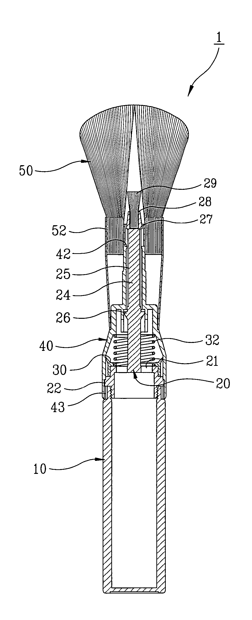
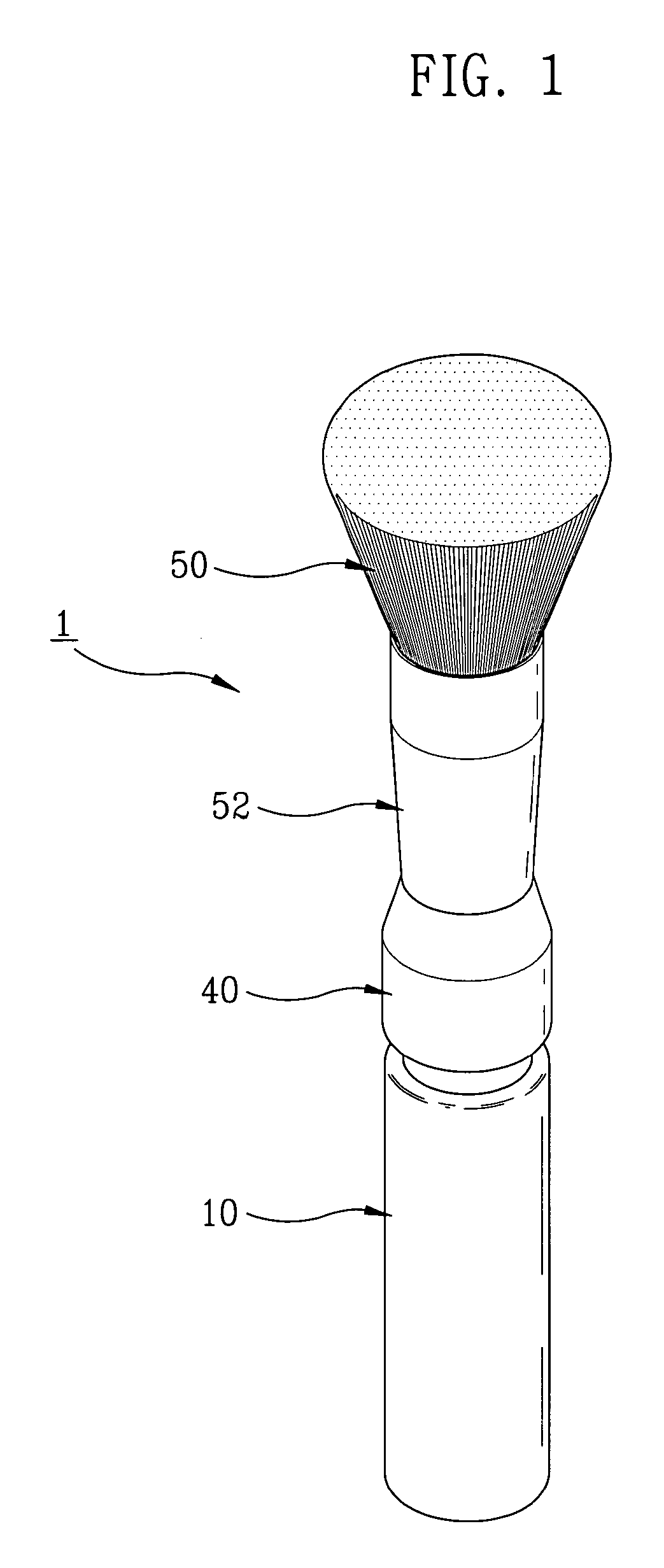
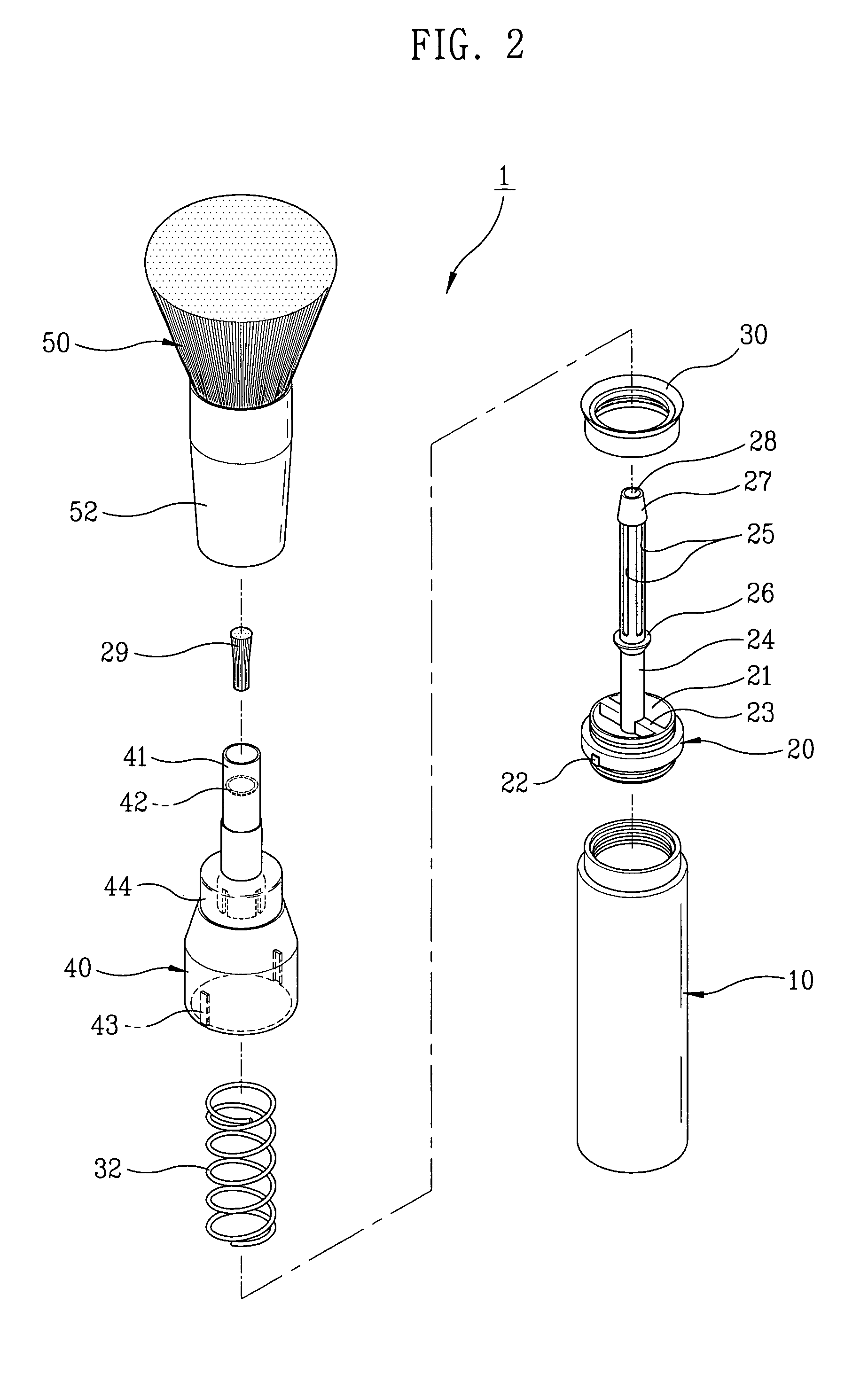
[0027]FIG. 1 is a perspective view illustrating an example of the present invention. FIG. 2 is an exploded perspective view illustrating the example of the present invention. FIG. 3 is a sectional view of FIG. 1 taken along Line A—A, and FIG. 4 is a sectional view of FIG. 1 showing the present invention with the main body thereof pushed up.

[0028]With regard to a cosmetics brush 1 of the present invention, cosmetics powder is discharging in a certain amount to a brush member 50 through vertical grooves 25 formed around a movable bar 24 by following the steps of: gripping an upper movable body 40 located at bottom portion of the brusher member 50 with one hand while pushing up a main body 10 by the other hand to enable the main body ...


PUM


Abstract

A cosmetic brush for applying make-up which includes a brush member, a main body located at the lower portion of the brush member and a movable bar connected to an intermediate coupler and reciprocally disposed to generate air pressure and to discharge cosmetic powder from the main body to the brush member by pushing up the main body when applying the make-up, wherein the movable bar includes vertical grooves and a press-ring and can move up and down by pushing the main body combined with the intermediate coupler containing the movable bar, so that the cosmetic powder housed in the body is conveyed through a powder transport duct positioned at the top portion of an upper movable body through the vertical grooves in the movable bar formed on top portion of the intermediate coupler and then distributes the cosmetic to the brush member side in a desirable distribution, resulting in improved convenience for the make-up user with an easier and simpler operation.

Description

[0001]This non-provisional application claims priority under 35 U.S.C. § 119(a) based on Patent Application No. 2004-0013344 filed in Korea on Feb. 27, 2004, the subject matter of which is herein incorporated by reference.BACKGROUND OF THE INVENTION[0002]1. Field of the Invention[0003]The present invention relates to a cosmetics brush, more particularly, a cosmetics brush for applying make-up including a brush member, a main body located at lower portion of the brush member and a movable bar connected to an intermediate coupler and for moving reciprocally to generate air pressure and to discharge cosmetic powder out of the main body to the brush member by pushing up the main body for applying the make-up The movable bar which includes vertical grooves, can be moved up and down by pushing the main body combined with the intermediate coupler having the movable bar, so that the cosmetic powder, housed in the main body, passes a powder transport duct positioned on the top portion of an ...

Claims


Application Information

Patent Timeline
Patent Type & Authority Patents(United States)
IPC IPC(8): A45D44/18A45D33/00A45D34/02A45D34/04A46B7/02A46B11/00A46B17/04
CPCA45D34/02A46B7/023A46B11/0055A46B17/04A46B2200/1046
Inventor BYUN, YOUNG-CHUL
Owner BYUN YOUNG CHUL
Why Eureka
Try Eureka