
Articulated seating mechanism

a seating mechanism and articulation technology, applied in the direction of chairs, movable seats, rocking chairs, etc., can solve problems such as sacrificing comfor

Active Publication Date: 2007-06-26
SMARTMOTION TECHNOLGY +1
View PDF20 Cites 57 Cited by
  • Summary
  • Abstract
  • Description
  • Claims
  • Application Information

AI Technical Summary

Benefits of technology

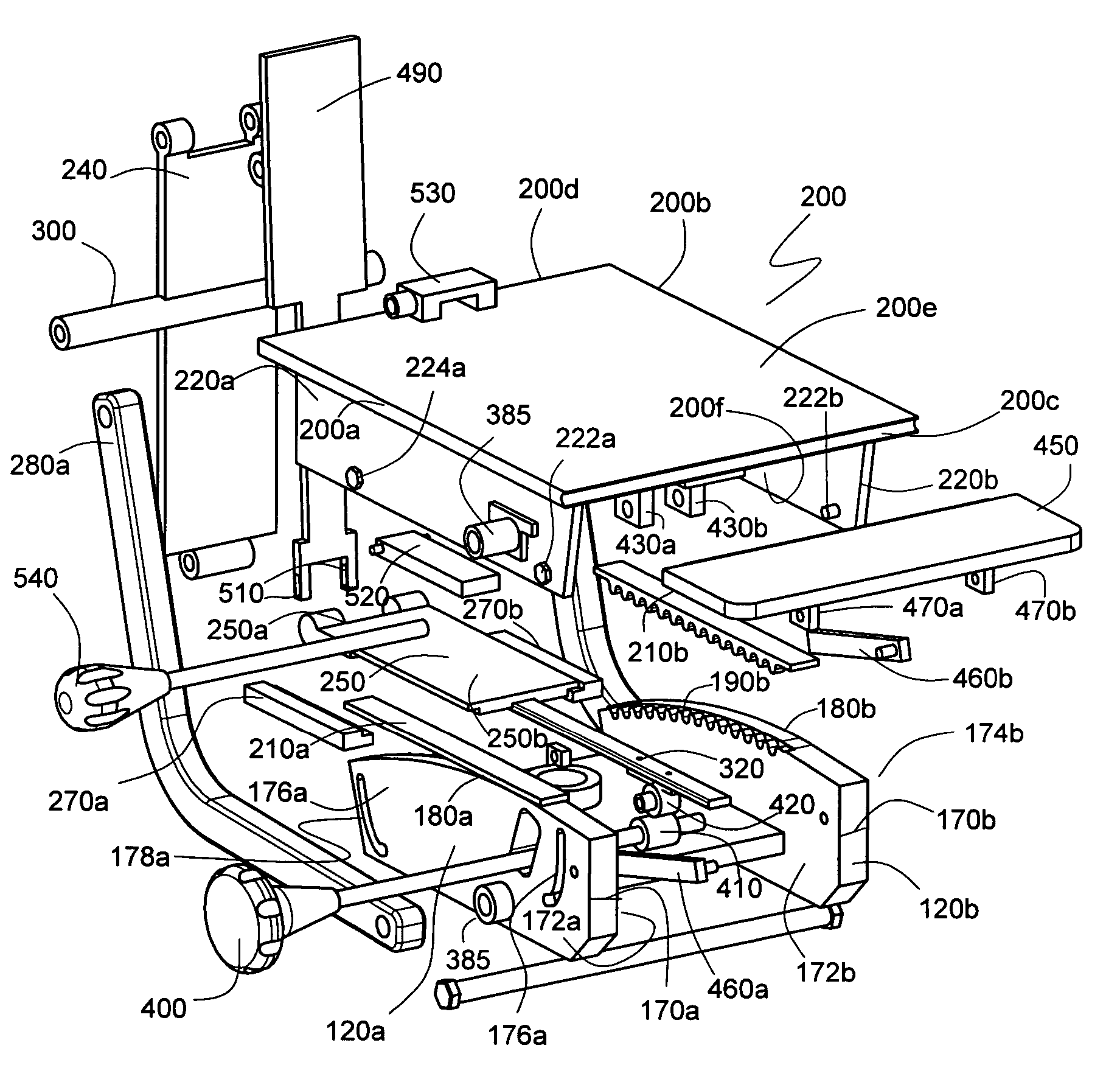
[0015]It is an object of the present invention to provide an adjustable ergonomic seat, and more particularly, an articulated rocking mechanism by which a separate caster base member, a seat, a back and optional arm rests can be attached to produce a completed tilting ergonomic chair. A chair incorporating the inventive apparatus provides a user means to move from a reclining position to a task-oriented position with a synchronous seat-to-back motion ratio of approximately 1:2. It makes use of a tilt mechanism having a moving fulcrum and allows a user to adjust both a preferred relaxation point and a range of motion.
[0016]Another object of the present invention is to provide a seating mechanism that integrates the seat and back to impart a predetermined synchronous movement that requires no external energy control sources such as springs to counteract the changing gravitational forces acting on a reclining user.
[0017]A further object of the inventive apparatus is to provide a seating mechanism with a self-balancing feature that accommodates a large range of movement and that also allows the user a continuous angular variation regardless of the user's size or body weight.

Problems solved by technology

A more challenging aspect in developing truly ergonomic chairs has been in synchronizing, coordinating, and integrating back rest movement with seat plate movement without sacrificing comfort or allowing for dangerous or otherwise awkward seating positions.

Method used


Image

  • Articulated seating mechanism
  • Articulated seating mechanism
  • Articulated seating mechanism

Examples


Embodiment Construction

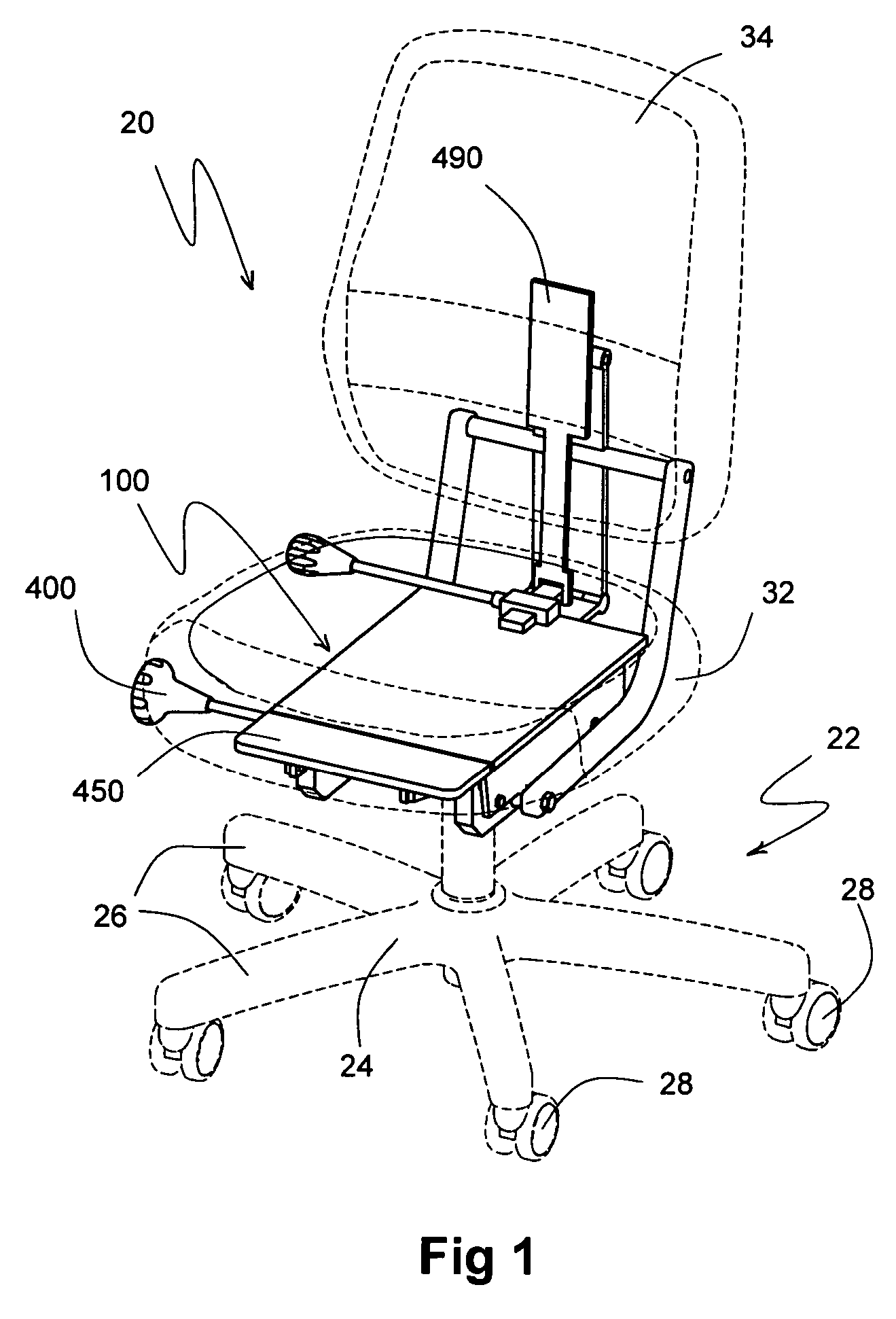
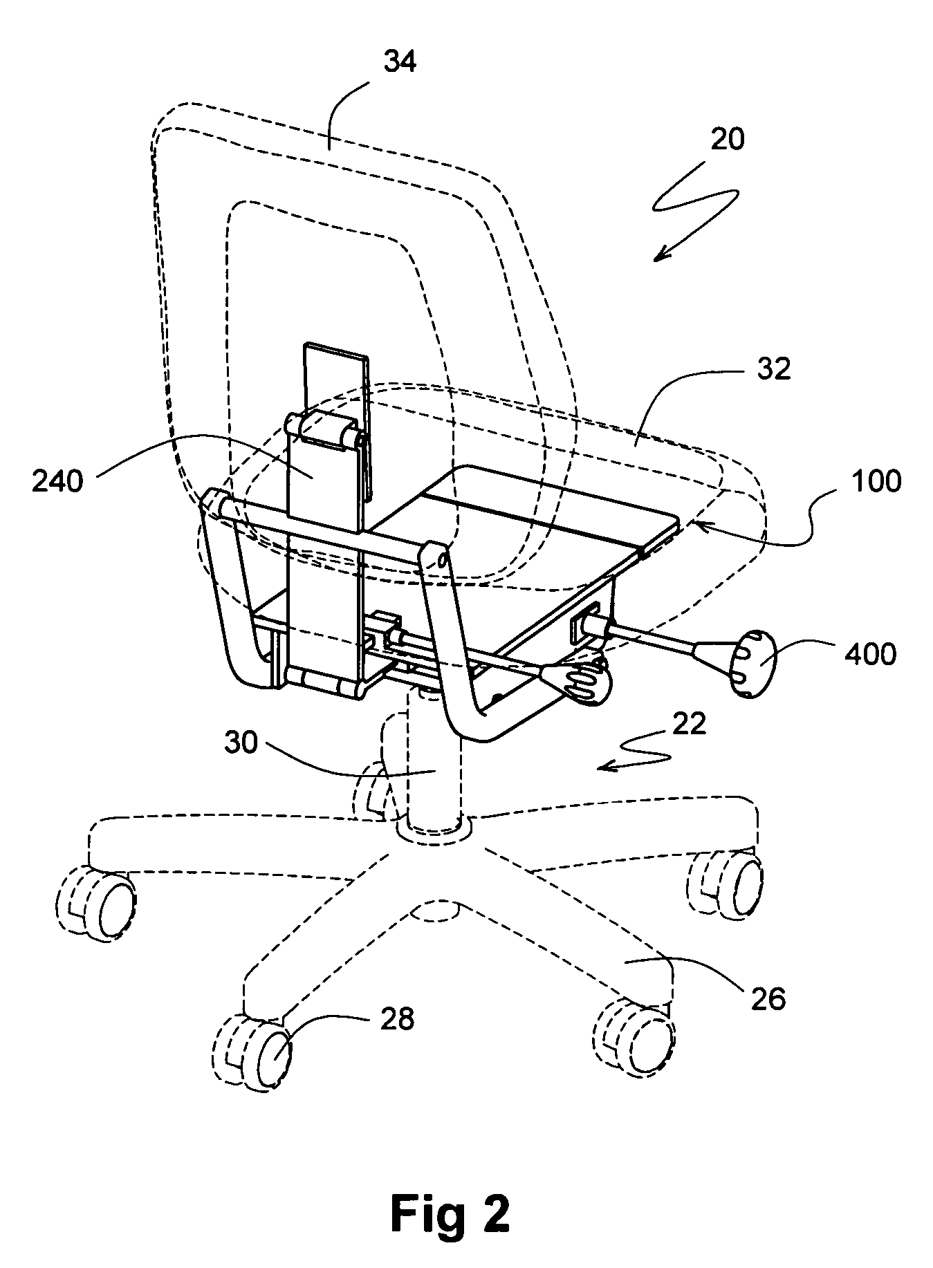
[0151]Referring to FIGS. 1 through 12, wherein like reference numerals refer to like components in the various views, there is illustrated therein a new and improved articulated seating mechanism, the first preferred embodiment of which is generally denominated 100 herein. FIG. 1 is an upper left front perspective view of an ergonomic chair incorporating the articulated seating mechanism of the present invention, while FIG. 2 is an upper right rear perspective view thereof. In these views the inventive seating mechanism is shown incorporated into an office chair 20. As with most office chairs currently available, the chair shown includes a pedestal 22 having a caster base 24 with a plurality of legs 26 and corresponding casters 28. The pedestal includes a telescoping extendable center post 30 on which the seating portion of the chair is supported. The chair also includes a seat cushion 32 and back cushion 34. These conventional features are shown in dashed lines and show a primary p...


PUM


Abstract

An articulated seating mechanism including a rocker base, a seat plate, and a pair of side rails, each having an arcuate side. The side rails may be disposed downwardly from the seat plate or upwardly from the rocker base. First and second arcuate gear portions are disposed on the arcuate side of each of the side rails and a first and second substantially flat or linear gear racks are affixed either to the underside of the seat plate or the upper side of the rocker base, so as to bring the linear gears and the arcuate gears into intermeshing relationship. A back support is pivotally connected to the seat plate and to first and second back links, and the back links are pivotally connected to the rocker base to provide a rocking motion of the seat plate and a dynamic synchronous adjustment of the angular variation between the seat plate and the back support. The linear gear racks move in a tangent to the arcuate gear portions to provide a moving fulcrum during rocking movements. No springs or other force means are necessary to assist in moving easily from a reclined position to task.

Description

CROSS REFERENCE TO RELATED APPLICATIONS[0001]The present application claims the benefit of the filing date of U.S. Provisional Patent Application, Ser. No. 60 / 459,889, filed Apr. 2, 2003.STATEMENT REGARDING FEDERALLY SPONSORED RESEARCH OR DEVELOPMENT[0002]Not applicable.REFERENCE TO A MICROFICHE APPENDIX[0003]Not applicable.TECHNICAL FIELD[0004]The present invention relates generally to adjustable chairs, more particularly to an articulated rocking mechanism for a tilting ergonomic chair.BACKGROUND INFORMATION AND DISCUSSION OF RELATED ART[0005]Adjustable chairs are well known in the art. In fact, adjustable office seating has now reached a high level of sophistication and maturity. Elements of contemporary ergonomic chairs have been in use for centuries and technological developments can be seen as early as the late 19th century when, for example, innovators focused on improving the back and forth rocking movement possible in chairs. Exemplary patents include U.S. Pat. No. 273,630 ...

Claims


Application Information

Patent Timeline
IPC IPC(8): A47C3/027A47C1/032
CPCA47C1/03255A47C3/027A47C1/03233A47C1/03272
Inventor WELLS, HAROLD G.
Owner SMARTMOTION TECHNOLGY
Learn More