Cooling circuit for cooling neck ring of preforms

a cooling circuit and preform technology, applied in the field of injection molding of preforms, can solve the problems of undesirable non-uniform cooling of the neck ring, and achieve the effects of uniform cooling, controlled cooling of the preform neck ring, and reducing the risk of injury

Inactive Publication Date: 2007-06-26
HUSKY INJECTION MOLDING SYST LTD
View PDF10 Cites 30 Cited by
  • Summary
  • Abstract
  • Description
  • Claims
  • Application Information

AI Technical Summary

Benefits of technology

[0008]The present invention also provides a modular construction of the neck ring insert that enables it to combine features of strength and ease of manufacturing with the ability to readily change the cooling channels to provide the most desirable cooling for each different type of neck ring.
[0011]The present invention also provides a neck ring insert that permits controlled cooling of the preform neck ring and, more particularly, more uniform cooling across the neck ring of the preform.

Problems solved by technology

The non-uniform cooling of the neck ring is undesirable.

Method used


Image

  • Cooling circuit for cooling neck ring of preforms
  • Cooling circuit for cooling neck ring of preforms
  • Cooling circuit for cooling neck ring of preforms

Examples


Embodiment Construction

[0025]Preform molds typically comprise a stack of mold inserts. Each insert forms a part of a preform being molded. The insert stack is carried by two or more mold plates supported in a mold shoe. A hot runner manifold distributes injected plastic melt from a central infeeding sprue to hot runner nozzles connected to the molding cavities formed in each insert stack. A cold half of the mold includes the stack of mold inserts and the portion of the mold shoe on which they are mounted. The hot half of the mold includes the hot runner assembly including sprue bush and nozzles and the mold plates adjacent to the manifold.

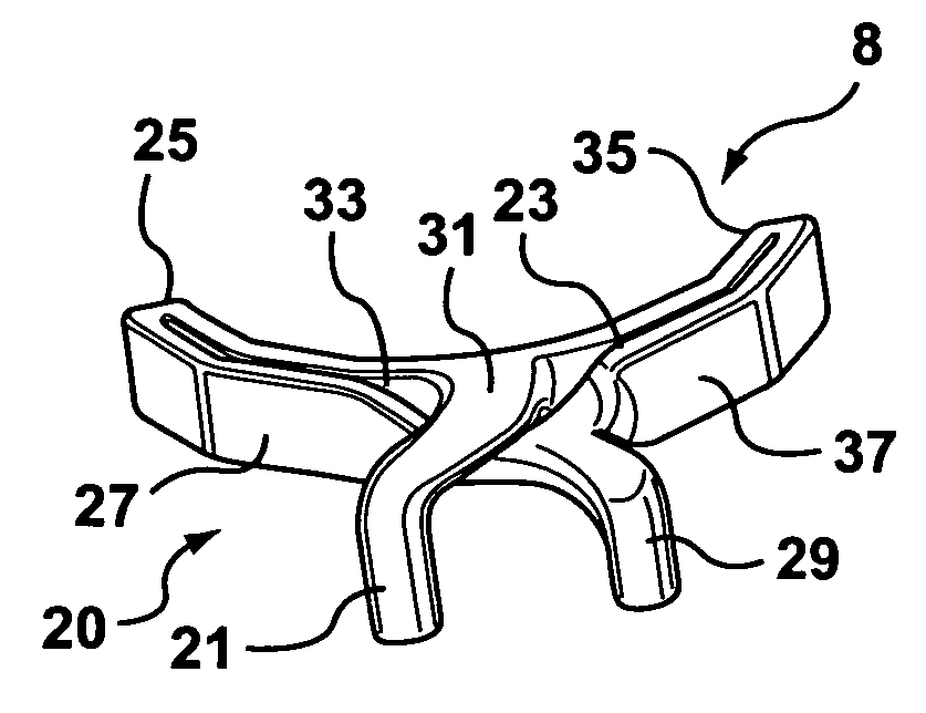
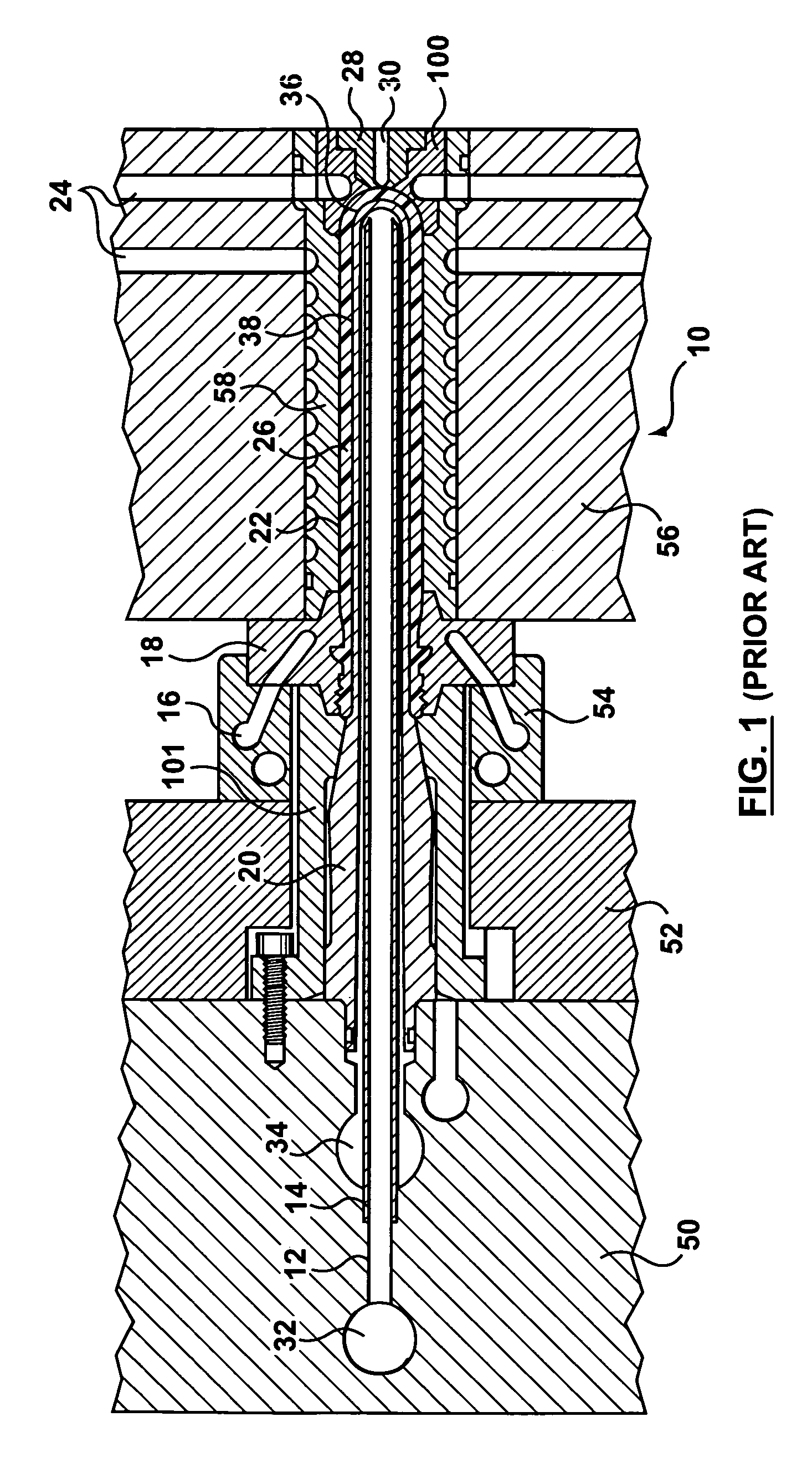
[0026]FIG. 1 shows a portion of a prior art preform mold stack 10 including core cooling channel 12, core cooling tube 14, neck ring cooling channels 16, neck rings 18, core 20, lock ring 101, mold cavity 22, cavity insert 58 and mold cooling channels 24 that extend circumferentially around the cavity. FIG. 1 also shows PET preform 26, mold gate insert 100 and injection ...


PUM

PropertyMeasurementUnit
porosityaaaaaaaaaa
circumferenceaaaaaaaaaa
thermally conductiveaaaaaaaaaa

Abstract

A cooling circuit for a neck ring of a preform is conformed to the surface of the neck ring by providing a neck ring in two parts. The first part supports the neck ring and provides strength and durability to the neck ring insert. The second part is formed of porous steel impregnated with highly thermally conductive metal and includes a cooling channel that provides substantially uniform cooling around the neck ring of the preform.

Description

BACKGROUND OF INVENTION[0001]1. Field of the Invention[0002]The present invention relates, generally, to the injection molding of preforms, and more particularly, but not exclusively, the invention relates to a mold insert for forming a neck ring on the preform and a method for making a mold insert.[0003]2. Background Information[0004]U.S. Pat. No. 5,599,567 to Gellert describes a neck ring insert for a perform mold that has a contoured cooling channel in the insert. The cooling circuit described in Gellert moves the coolant vertically in an outer channel and then horizontally to an inner channel that forms an inner cooling loop. The cooling loop has both horizontal and vertical sections and finally connects to an outer discharge channel. This channel construction causes more rapid cooling of the portions of the neck ring near the beginning of the cooling channel. The non-uniform cooling of the neck ring is undesirable.[0005]U.S. Reissue Pat. No. 38,396 to Gellert describes a method...

Claims


Application Information

Patent Timeline
Patent Type & Authority Patents(United States)
IPC IPC(8): B29C45/73B29C45/17B29C45/33
CPCB29C45/7312B29C45/33B29C2033/042B29K2105/253B33Y80/00B33Y70/00
Inventor NIEWELS, JOACHIM JOHANNESZURAW, MICHAEL K.LI, GUOMING
Owner HUSKY INJECTION MOLDING SYST LTD
Why Eureka
Try Eureka