Anchoring element for securing a rod on a vertebra

a technology of anchoring element and rod, which is applied in the field of anchoring element for fastening rod, can solve the problems of difficult practice, difficult to screw the respective one of the locking screws, and the pin can only be designed very small on the inner side of the holding ridge, so as to achieve easy and fast fitting and reliably absorb the force generated

Inactive Publication Date: 2007-06-26
METZ STAVENHAGEN PETER
View PDF14 Cites 50 Cited by
  • Summary
  • Abstract
  • Description
  • Claims
  • Application Information

AI Technical Summary

Benefits of technology

[0015]In view thereof, it is the object of the present invention to provide an anchoring elemen...

Problems solved by technology

It has been found that this is very difficult to carry out in practice because both inserting the securing element into the grooves and screwing the securing element onto the holding device require great dexterity, the vertebral body and/or the rod concurrently having to be prevented from coming out of place in the meantime.
In this case also, it has been found very tedious to screw the respective one of the locking screws into the corresponding buttress thread while maintaining the spine and/or the rod in the desired position until the loc...

Method used


Image

  • Anchoring element for securing a rod on a vertebra
  • Anchoring element for securing a rod on a vertebra
  • Anchoring element for securing a rod on a vertebra

Examples


first embodiment

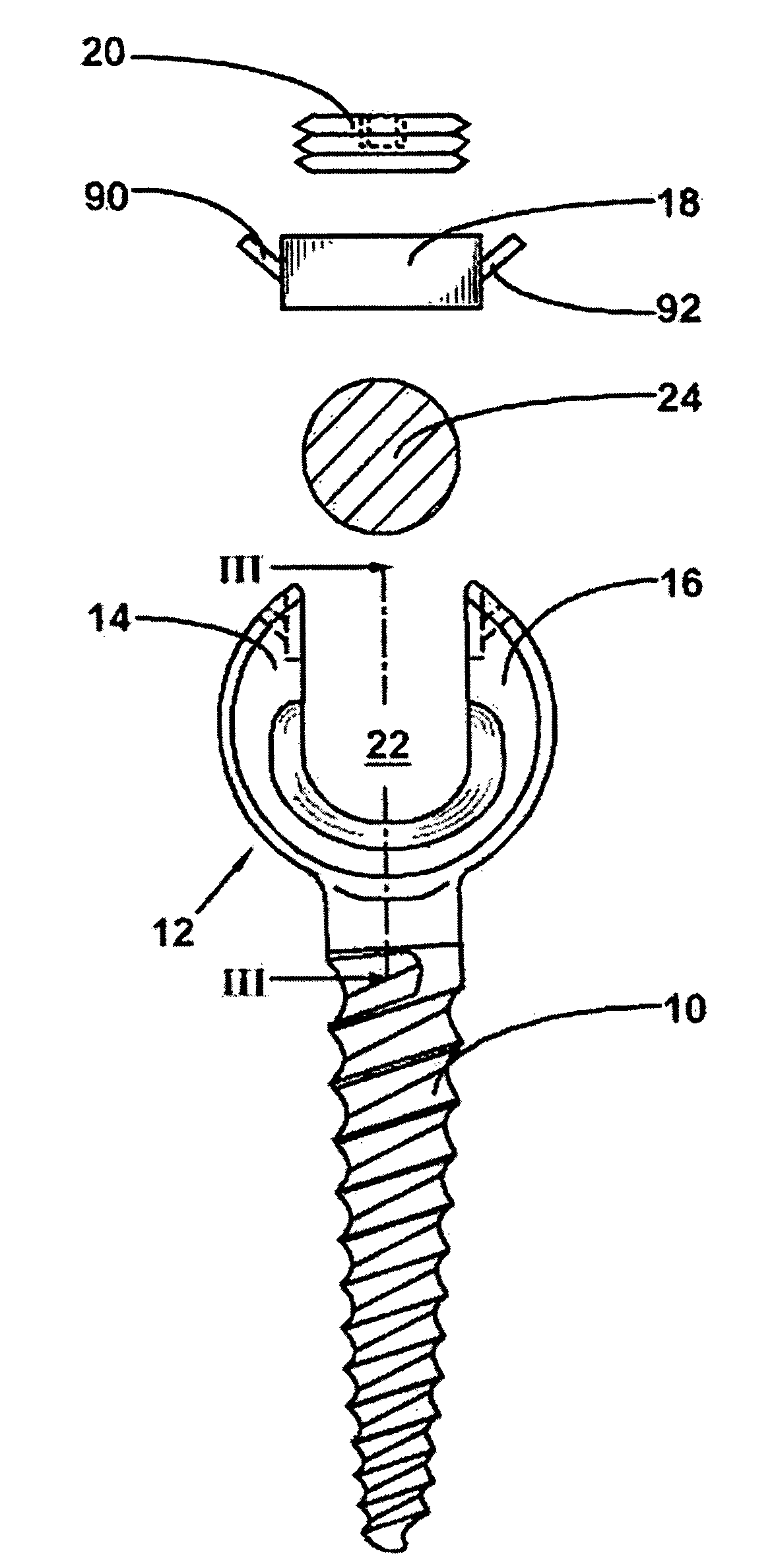
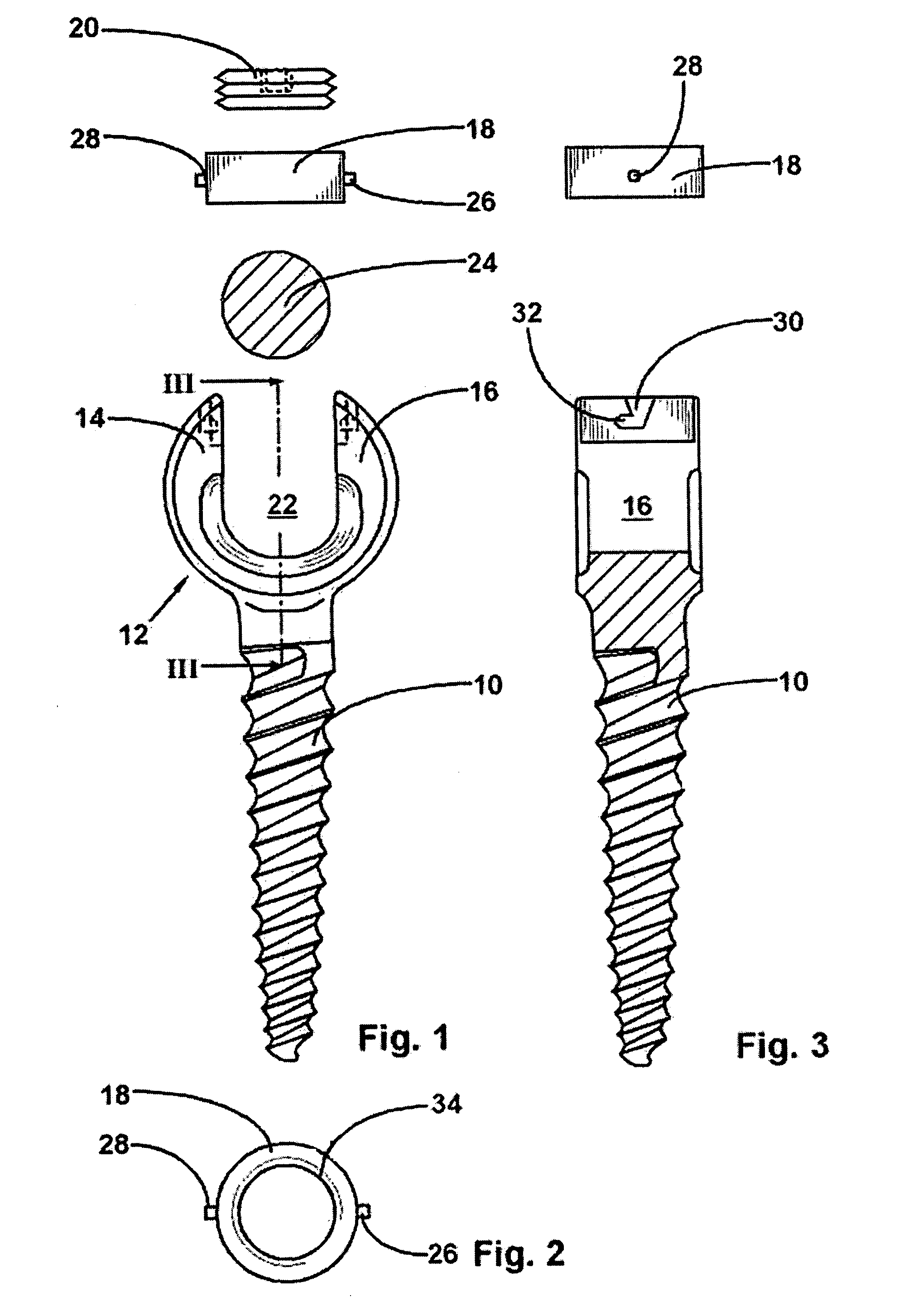
[0064]The FIGS. 1 to 3 illustrate an anchoring element for insertion into the vertebral bone that is configured to be a pedicle screw, said anchoring element including a threaded shank 10 as well as a U-shaped holding device 12 having two substantially parallely disposed holding ridges 14, 16, a ring element 18 and a locking element 20 implemented in the form of a grub screw. In the holding device 12 there is provided a receiving slot 22 for receiving a rod 24 that is fixed by the securing element consisting of the locking element 20 and the ring element 18.

[0065]In this embodiment, two bayonet pins 26, 28 are formed on opposing sides of the ring element 18 so as to project radially, said pins being insertable into a corresponding entrance 30 formed on the inner side of the holding ridges 14, 16 and into a holding element 32. The ring element 18 is inserted from the top by its two pins 26, 28 into the entrance 30 which is open toward the top and is pushed down to the bottom of the e...

second embodiment

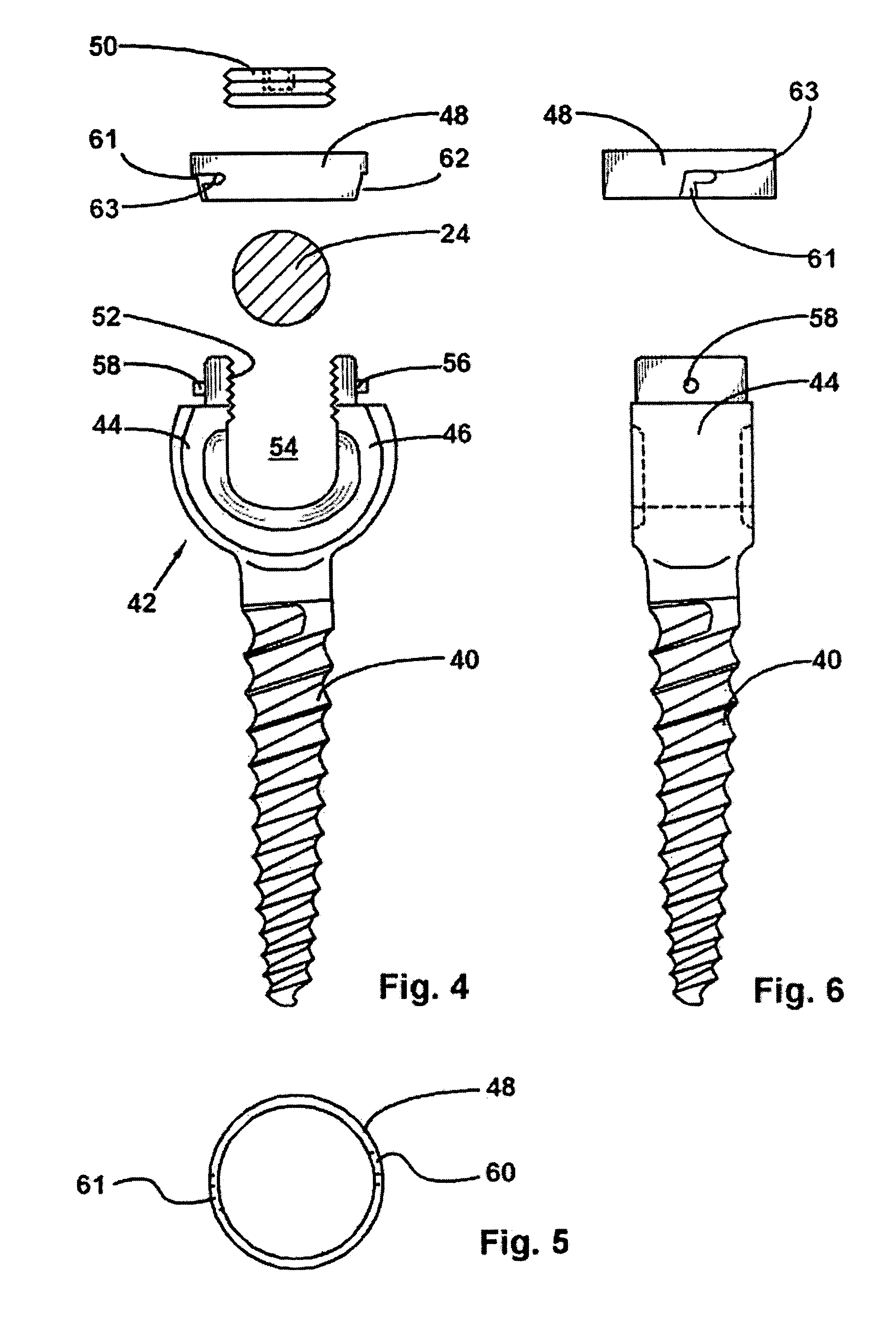
[0068]The FIGS. 4 to 6 illustrate an anchoring element of the invention that is also configured to be a pedicle screw. Again, said anchoring element is composed of a threaded shank 40 for mounting the anchoring element in the vertebral bone, of a U-shaped holding device 42 having two substantially parallely disposed holding ridges 44, 46, a ring element 48 and a locking element 50 implemented in the form of a grub screw. In this embodiment, an internal thread 52 for receiving the locking element 50 configured to be a grub screw is formed on the respective inner sides of the holding ridges 44, 46. In order to prevent the radial forces acting onto the holding ridges 44, 46 from causing the holding ridges 44, 46 to bend apart in this embodiment, the ring element 48 is placed outside of and around the holding ridges 44, 46.

[0069]In this embodiment also, a rod 24 receiving slot 54 is formed in the holding device 42, said rod being locked in the desired position by the locking element 50....


PUM


Abstract

An anchoring element for fastening a rod of a device for adjusting a human or animal spine to a vertebral bone, and having a holding device that is substantially U-shaped and includes two substantially parallely disposed holding ridges, a rod receiving slot being formed therein, and a securing element acting against the rod accommodated in the receiving slot. The securing element includes a locking element and a ring element and the ring element is mountable to the free end of the holding ridges by means of a single turn coupling system. Further a partial thread can be provided on opposing sides of the holding ridges and two opposing thread portions and two opposing entrance portions can be configured on the circumference of the ring element the diameter of the securing element in the region of the entrance portions not exceeding the core diameter of the thread portion so that the thread portions are engageable with the partial threads of the holding ridges and the thread portions and the partial threads comprise buttress threads.

Description

BACKGROUND OF THE INVENTION[0001]DE 202 07 852.3 dated May 21, 2002 and DE 202 07 850.7 dated May 21, 2002[0002]1. Field of the Invention[0003]The present invention relates to an anchoring element for fastening a rod of a device for adjusting a human or animal spine to a vertebral bone, said anchoring element having a holding device that is substantially U-shaped and includes two substantially parallely disposed holding ridges, a rod receiving slot being formed therein, and a securing element acting against the rod accommodated in the receiving slot.[0004]2. Description of the Prior Art[0005]A pedicle screw the threaded shank of which is anchorable within a vertebral bone and which comprises at its end protruding from the vertebral bone a U-shaped holding device having two parallely oriented holding ridges is known from DE 94 02 839. Between the holding ridges there is formed a slot for receiving a distraction or compression rod that can be secured and fixed by means of a securing e...

Claims


Application Information

Patent Timeline
IPC IPC(8): A61B17/70
CPCA61B17/7032
Inventor METZ-STAVENHAGEN, PETER
Owner METZ STAVENHAGEN PETER
Why Eureka
Try Eureka