Mechanism to improve stent securement

a technology of stent and stent axis, applied in the field of stent securement, can solve the problems of reducing the axial increasing the risk of the stent shifting position on the catheter, and reducing the strength of the stent. the effect of preventing the movement of the sten

Inactive Publication Date: 2007-06-26
BOSTON SCI SCIMED INC
View PDF59 Cites 237 Cited by
  • Summary
  • Abstract
  • Description
  • Claims
  • Application Information

AI Technical Summary

Benefits of technology

[0014]In one embodiment, the present invention is directed to a device for preventing stent movement during delivery. The device includes a securement connector arranged to engage a catheter, at least one flexible connecting member and at least one locking member arranged to engage a portion of a stent. The device is capable of constraining portions of the stent throughout expansion of the stent.

Problems solved by technology

Thus, present stents commonly combine a thin wall thickness with high flexibility, which leads to various drawbacks associated with stent delivery.
Stents with a reduced wall thickness typically have reduced strength in all directions.
Therefore, the stent has an increased risk of shifting positions on the catheter as it is maneuvered through the body.
Reducing stent wall thickness may also reduce the axial strength of the stent.
Lowered axial rigidity allows the stent to more easily pass through curved bodily vessels but can also lead to difficulty in stent placement during expansion.
When a stent with low axial rigidity is expanded by a balloon catheter, the stent may experience increased shortening or lengthening.
Conversely, if balloon inflation begins at the center and moves outwardly, the stent often experiences lengthening upon deployment.
These known methods typically release the stent early in the balloon inflation procedure and do not maintain the axial dimensions of the stent during inflation.

Method used


Image

  • Mechanism to improve stent securement
  • Mechanism to improve stent securement
  • Mechanism to improve stent securement

Examples


Embodiment Construction

[0035]While this invention may be embodied in many different forms, there are described in detail herein specific preferred embodiments of the invention. This description is an exemplification of the principles of the invention and is not intended to limit the invention to the particular embodiments illustrated.

[0036]For the purposes of this disclosure, like reference numerals in the figures shall refer to like features unless otherwise indicated.

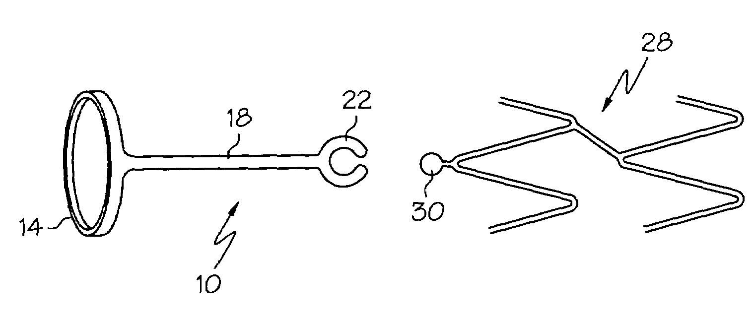
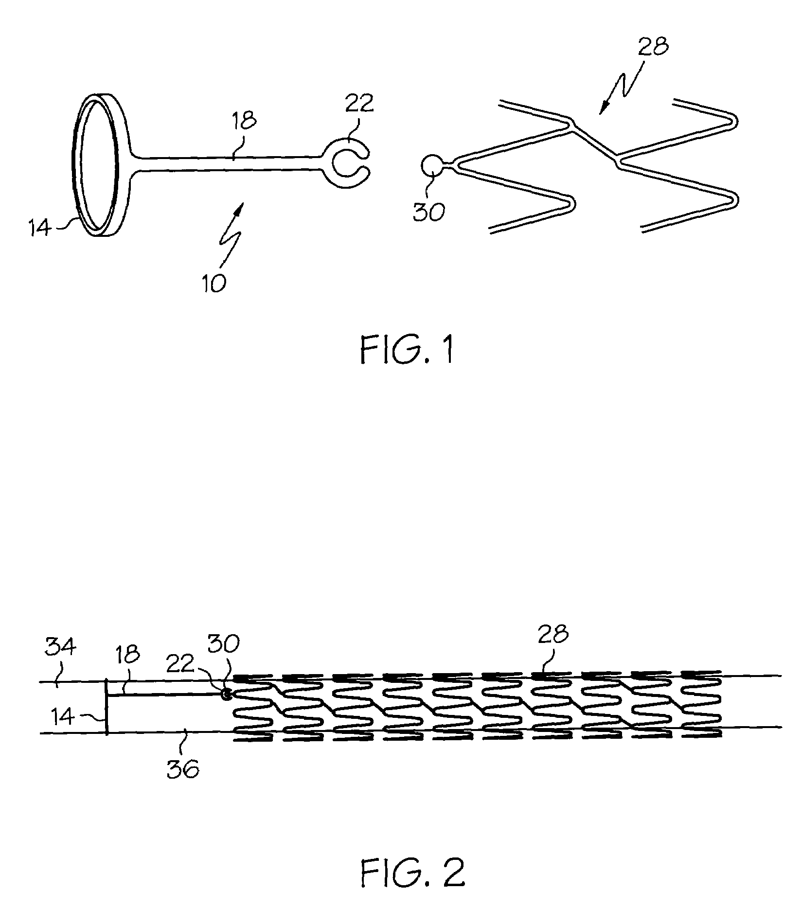
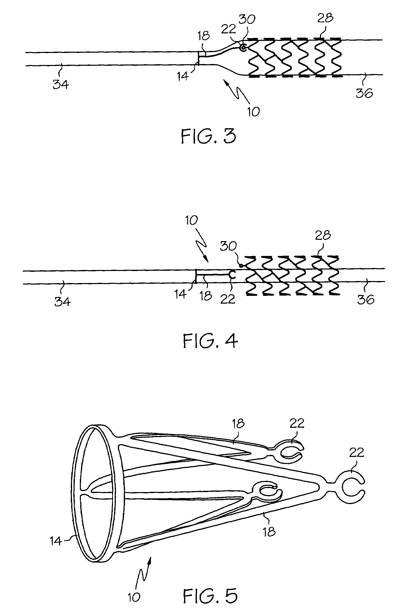
[0037]In one embodiment, the present invention is directed to a stent securement member 10 as depicted in FIGS. 1-4. The securement member 10 generally comprises a securement connector 14, a flexible connecting member 18 and a locking or engaging member 22.

[0038]The securement member 10 may be used with a stent 28 having an engagable portion 30 desirably located at the one or both ends of the stent 28. The locking member 22 is arranged to engage the stent engagable portion 30 and thereby constrain movement of the stent 28. Desirably, moveme...


PUM


Abstract

The present invention comprises a securement member to improve securement of a stent upon an expandable balloon and delivery catheter, and to constrain portions of the stent before and during stent deployment. Generally, the securement member comprises a securement connector arranged to engage a catheter, at least one flexible connecting member coupled to the securement connector, and a locking member arranged to engage a portion of a stent.

Description

BACKGROUND OF THE INVENTION[0001]Stents and stent delivery assemblies are utilized in a number of medical procedures and situations, and as such their structure and function are well known. A stent is a generally cylindrical prosthesis introduced via a catheter into a lumen of a body vessel in a configuration having a generally reduced diameter, and then expanded to the diameter of the vessel. In its expanded configuration, the stent supports and reinforces the vessel walls while maintaining the vessel in an open, unobstructed condition.[0002]Both self-expanding and inflation expandable stents are well known and widely available in a variety of designs and configurations. Inflation expandable stents are crimped to their reduced diameter about the delivery catheter, maneuvered to the deployment site, and expanded to the vessel diameter by fluid inflation of a balloon positioned on the delivery catheter. The present invention is particularly concerned with delivery and deployment of i...

Claims


Application Information

Patent Timeline
Patent Type & Authority Patents(United States)
IPC IPC(8): A61F2/06A61F2/00A61F2/82
CPCA61F2/91A61F2/915A61F2/95A61F2/958A61F2002/30428A61F2002/828A61F2230/0054A61F2002/91533A61F2002/91558A61F2002/91591A61F2002/9505A61F2002/9583A61F2220/0025A61F2002/91525
Inventor GREGORICH, DANIEL
Owner BOSTON SCI SCIMED INC
Why Eureka
Try Eureka