Sensor for detecting the direction of a magnetic field in a plane

a magnetic field and plane technology, applied in the direction of magnetic measurements, instruments, measurement devices, etc., can solve the problems of large sensor size, high cost, and inability to accurately detect the direction of the magnetic field in the plane, so as to achieve simple wiring and evaluation, the effect of increasing the accuracy of angle determination

Active Publication Date: 2007-06-26
MELEXIS TECH NV
View PDF4 Cites 106 Cited by
  • Summary
  • Abstract
  • Description
  • Claims
  • Application Information

AI Technical Summary

Benefits of technology

[0011]The accuracy of the angle φ determination can be increased when the value of the angle φ determined from the output signals of the magnetic field sensor is corrected by means of a characteristic curve. The characteristic curve is preferably available in the form of a table whereby each value determined from the output signals is assigned to the corresponding corrected value.
[0012]It is practical to provide two magnetic field sensors in pairs per measuring axis. Their output sign

Problems solved by technology

As an accurate analogue quotient formation is very complex to implement, the quotient formation is often done in a digital way for example by means of the iterative CORDIC algorithm.
The digital quotient formation is time-consuming and therefore slow.
Such a sensor is therefore large, expensive and slow.
Here, a further problem exists in that the strength of

Method used


Image

  • Sensor for detecting the direction of a magnetic field in a plane
  • Sensor for detecting the direction of a magnetic field in a plane
  • Sensor for detecting the direction of a magnetic field in a plane

Examples


Embodiment Construction

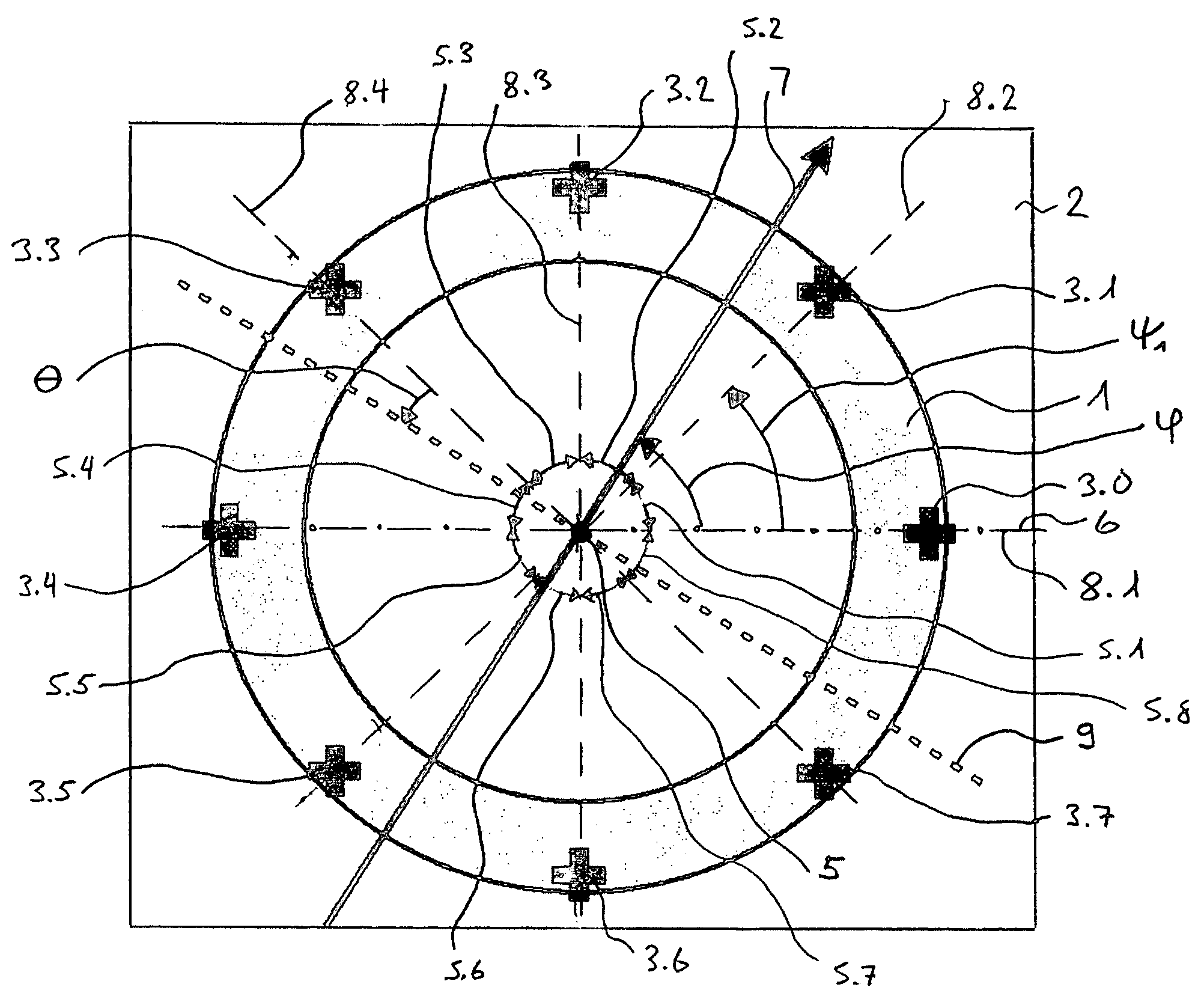
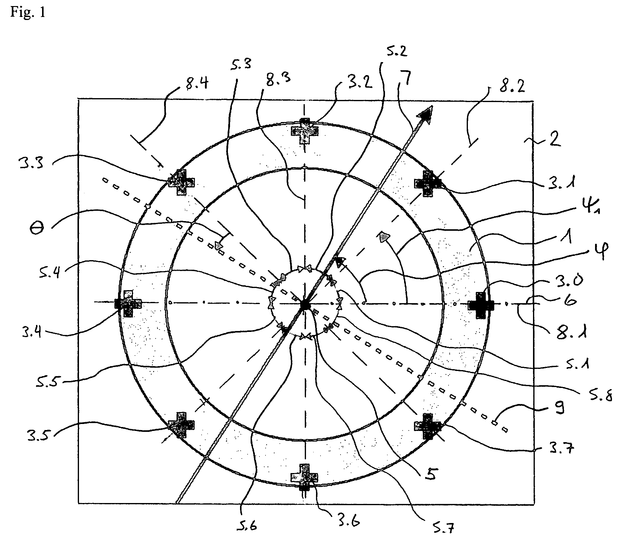
[0018]FIG. 1 shows a plan view of a sensor in accordance with the invention in a preferred embodiment with a magnetic field concentrator 1. The sensor consists of a semiconductor chip 2 with the flat ring-shaped or disc-shaped magnetic field concentrator 1 arranged on its upper side and a number of n magnetic field sensors 3.m, whereby the index m assumes the values of 0 to n−1, as well as logic, amplifier and evaluation circuits. The number n of the magnetic field sensors is preferably an integral power of the number 2. In the example, n=23=8. If the magnetic field concentrator 1 is disc-shaped, then it preferably has a uniform thickness. However, in the middle it can be formed thicker than at the edge 4. The magnetic field concentrator 1 therefore works as a concentrator for the two components of the magnetic field that lie in the plane designated as xy plane formed by it. The magnetic field sensors 3.0 to 3.(n−1) are arranged at regular angular distances along the edge 4 of the m...


PUM


Abstract

The invention relates to a sensor for detecting the direction of a magnetic field in a plane whose direction can be defined by the indication of a polar angle ?. Said sensor comprises a number of n magnetic field sensors (3.0 to 3.7). A measurement axis (8.1 to 8.4) is assigned to each magnetic field sensor in such a manner that the absolute value of the output signal of the magnetic field sensor is largest when the magnetic field runs parallel to the measuring axis. All measuring axes intersect at a common point (5). The number k of measuring axes is equal to at least three. An operating mode is provided during which two magnetic field sensors are selected for calculating the angle ?. These two magnetic field sensors belong to different measuring axes, and the values of the output signals thereof are less than those of the output signals of the magnetic field sensors belonging to the other measuring axes.

Description

CROSS REFERENCE TO RELATED APPLICATION[0001]The present application is related to and claims priority of the PCT application number PCT / EP03 / 10503 entitled Sensor for detecting the direction of a magnetic field in a plane, filed Aug. 22, 2003, the disdosure of which is herein incorporated by reference.FIELD OF THE INVENTION[0002]The invention concerns a sensor for detecting the direction of a magnetic field in a plane.BACKGROUND OF THE INVENTION[0003]Such sensors are suitable for example for measuring the direction of a magnetic field in a plane. Nowadays, sensors are almost exclusively used that measure the components of the magnetic field in relation to two orthogonal coordinate axes. These sensors contain magnetic field sensors such as magnetoresistive components (e.g. Philips KMZ41) or Hall elements (e.g. Sentron 2SA-10). The magnetic field sensors provide two analogue output voltages that are proportional to the sine or cosine function of the direction of the magnetic field. Th...

Claims


Application Information

Patent Timeline
IPC IPC(8): G01R33/02G01R33/00
CPCG01R33/02G01R33/077
Inventor POPOVIC, RADIVOJESCHOTT, CHRISTIAN
Owner MELEXIS TECH NV
Why Eureka
Try Eureka