System and method for determining range in 3D imaging systems

a three-dimensional imaging and range determination technology, applied in the field of objects, can solve the problems of complex approaches, high production costs, and inability to meet the requirements of the system to image remote objects

Active Publication Date: 2007-06-26
TOPCON POSITIONING SYST INC
View PDF31 Cites 110 Cited by
  • Summary
  • Abstract
  • Description
  • Claims
  • Application Information

AI Technical Summary

Problems solved by technology

However, adapting such systems to image remote objects challenges the sensitivity and speed of available devices.
The approaches to date have been complex and, therefore, expensive to produce and maintain.

Method used


Image

  • System and method for determining range in 3D imaging systems
  • System and method for determining range in 3D imaging systems
  • System and method for determining range in 3D imaging systems

Examples


Embodiment Construction

[0019]In the following detailed description of the preferred embodiments, reference is made to the accompanying drawings which form a part hereof, and in which is shown by way of illustration specific embodiments in which the invention may be practiced. It is to be understood that other embodiments may be utilized and structural changes may be made without departing from the scope of the present invention.

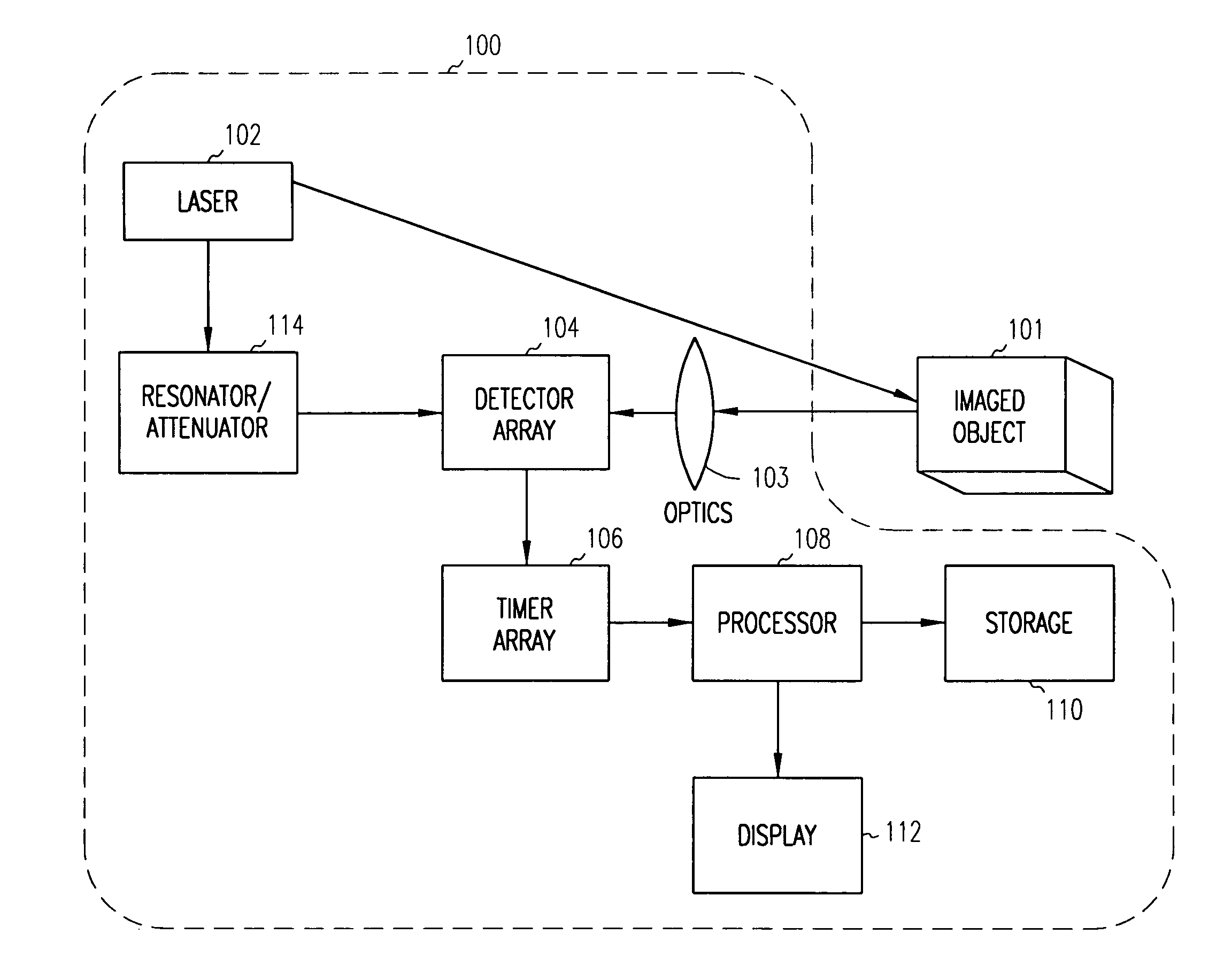
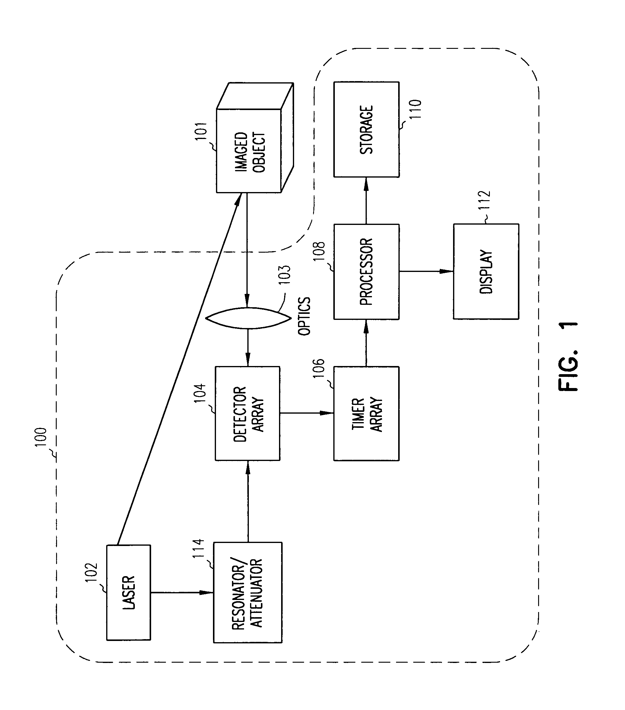
[0020]A representative system 100 for creating a high resolution three-dimensional image of a scene of interest 101 is shown in FIG. 1. A pulsed light source 102, typically a laser, is directed toward target scene 101. Some of the light is reflected back from the scene. An array of detectors 104 receives the light from portions of the scene. The distance from the system to the portion of the scene 101 in the field of view of a single detector is determined by the time required for the light to illuminate that portion and then return to the detectors 104.

[0021]In the embodiment show...


PUM


Abstract

A system and method of imaging an object. An array of detectors is mounted in an image plane. Each detector in the array of detectors is connected to a timing circuit having an interpolator, wherein the interpolator includes a first circuit which charges a first capacitor at a different rate than it discharges. An optical pulse is transmitted toward an object so that a portion of the optical pulse is reflected from the object as a reflected pulse and a first value representative of when the optical pulse was transmitted toward the object is recorded. The reflected pulse is detected at one or more detectors and a pulse characteristic of the pulse and a second value representative of when the reflected pulse arrived at the detector are recorded. Range to the object is then calculated as a function of the first and second values and the reflected pulse characteristic.

Description

CROSS-REFERENCE TO RELATED APPLICATION[0001]This application is related to U.S. patent application Ser. No. 10 / 886,079, entitled “System and Method for 3D Imaging,” filed on even date herewith, which is incorporated herein by reference.BACKGROUND OF THE INVENTION[0002]1. Field of the Invention[0003]This invention relates to imaging of objects using arrays of light detectors and, more particularly, to a system and method for determining range in three-dimensional imaging systems.[0004]2. Background Information[0005]Laser techniques, such as LADAR (Laser Detection and Ranging) or “LIDAR” (Light Detection and Ranging), are currently being used to image objects in three-dimensional image systems. Light, often from a laser source, is directed toward an object of interest. Reflected light from the object is then gathered and focused on one or more photodetectors.[0006]LADAR systems are capable of determining the distance to an object, for example, by timing the travel time of light pulses...

Claims


Application Information

Patent Timeline
Patent Type & Authority Patents(United States)
IPC IPC(8): G01C3/08G01S17/10G01S7/4865G01S17/894
CPCG01S7/4865G01S7/4868G01S17/10G01S17/89G01S7/497G01S17/894
Inventor DIMSDALE, JERRY
Owner TOPCON POSITIONING SYST INC
Why Eureka
Try Eureka